Students should refer to Electromagnetism ICSE Class 10 Physics Notes and solutions below. Our teachers have provided numerical problems and solutions for chapter Electromagnetism in ICSE Class 10 Physics. These notes are really useful if you are preparing for ICSE exams. concise physics class 10 solutions are also very important for Physics students.
ICSE Class 10 Physics Electromagnetism Numerical Problems
Students can refer to the Numerical Problems prepared for Chapter Electromagnetism in Class 10 ICSE. These notes will be really helpful for the students giving the Physics exam in ICSE Class 10. Our teachers have prepared these concept notes based on the latest ICSE syllabus and ICSE books issued for the current academic year. Please refer to Chapter wise notes for ICSE Class 10 Physics provided on our website.
Electromagnetism ICSE Class 10 Physics Revision Notes
Magnetic Effect of Current
Revision Notes
➢ Besides the heating effect and the chemical effect, current also has a magnetic effect associated with them.
➢ The experiments of Oersted and Ampere, on the effects of a current- carrying wire deflecting a compass needle led to the discovery of the magnetic effects of current.
➢ Magnetic field and field lines due to a straight conductor carrying current
(i) The magnetic field lines form concentric circles around the wire, with their plane perpendicular to the straight wire and with their centre lying on the wire.
(ii) If a is cardboard inserted perpendicular to the current carrying wire and some iron filings are sprinkled over the cardboard then iron filings arrange themselves in a curved pattern.
(iii) When the direction of current in the wire is reversed, the pattern of iron filings does not change, but the direction of deflection of the compass needle gets reversed. The north pole of the compass needle now points in a direction opposite to the previous direction showing that the direction of the magnetic field has reversed.
(iv) On increasing the current in the wire, the magnetic field lines become denser and the iron filings get arranged in circles up to a larger distance from the wire, showing that the magnetic field strength has increased and it is effective up to a larger distance.
➢ Right hand thumb rule :
If we hold the current carrying conductor in our right hand such that the thumb points in the direction of current then encircling of fingers will give the direction of the magnetic field.
➢ A simple rule for finding the direction of the magnetic field due to a current-carrying wire is the so-called Ampere’s swimming rule. According to this rule: Imagine a man, with his face downwards, swimming above the wire along the direction of flow of current. The north pole of the compass needle kept below the wire will be deflected towards his left hand.

➢ It is now believed that currents (i.e. moving charges) – and not magnetic poles – are the basic cause of all magnetism.
➢ The lines of force of the magnetic field due to a straight current-carrying wire are concentric around the wire.
➢ From the pattern of magnetic field lines, it is noted that
(i) In the vicinity of wire at P and Q, the magnetic field lines are nearly circular.
(ii) Within the space enclosed by the wire(i.e., between P and Q), the magnetic field lines are in the same direction.
(iii) Near the centre of the loop, the magnetic field lines are nearly parallel to each other, so the magnetic field may be assumed to be nearly uniform in a small space near the centre.
(iv) At the centre, the magnetic field lines are along the axis of the loop and normal to the plane of the loop.
(v) The magnetic field lines become denser (i.e., the magnetic field strength is increased) if
(a) the strength of the current in the loop is increased, and
(b) the number of turns in the loop increased.

➢ When a material is placed inside a coil carrying current, it will get magnetized. A bunch of nails or an iron rod placed along the axis of the coil can be magnetized by the current allowed to pass through the coil. Such magnets are called electromagnets.
➢ For finding the polarity of the two faces of a current-carrying circular coil, the following rule applies: When an observer, looking at the circular coil, finds the current to be flowing in the anticlockwise sense, that face of the coil behaves like the north-pole(N-pole) of the equivalent magnet. On the other hand, if the current is seen to flow in the clockwise sense, that face of the coil behaves like the south-pole (S-pole) of the equivalent magnet.
➢ The solenoid is made by closely winding a large number of turns of an insulated wire on a long cylindrical core.
➢ A current-carrying solenoid produces a uniform field close to its centre and its field is very similar to that of a bar magnet.

➢ The electromagnet consists essentially of a soft iron core around which a large number of turns of insulated wire are wound. It is a temporary magnet which can be magnetized or demagnetized, in a very short time, simply by switching ’ON’ or ‘OFF’ the current through it.
➢ Comparison of Electromagnet and Permanent Magnet :

➢ Uses of Electromagnet :
(i) It is used for lifting and transporting the large masses of iron scrap, girder, plates etc.
(ii) It is used for loading the furnace with iron.
(iii) It is used for separating the magnetic substances such as iron from debris and raw materials.
(iv) It is used for removing pieces of iron from wounds.
➢ An electromagnet has the following advantages over a permanent magnet :
(i) An electromagnet can produce a strong magnetic field.
(ii) The strength of the magnetic field of an electromagnet can easily be changed by changing the current (or the number of turns) in its solenoid.
(iii) The polarity of the electromagnet can be reversed by reversing the direction of current in its solenoid.
➢ It is not Ampere’s law when a current I passes through a conductor of length l placed in magnetic field B, then the force experienced is given by, F = IB/sin θ where θ is an angle between the length of the conductor and magnetic field.
➢ Fleming’s left hand rule: Stretch the forefinger, central finger and the thumb of your left hand mutually perpendicular to each other. If the forefinger indicates the direction of magnetic field, central finger indicates the direction of current then the thumb will indicate the direction of motion of conductor (i.e., force on conductor).
➢ D.C. Motor :
Its main parts are armature coil ABCD, split ring commutator S1 and S2, carbon brushes B1 and B2, horse shoe magnet and a d.c. source.
D The construction of the DC motor should move below the Principle and before “Ways of increasing the speed of the rotation of coil”.
It is a device, which converts electrical energy into mechanical energy.
Principle: A D.C. motor works on the principle that when an electric current is passed through a conductor placed normally in a magnetic field, a force acts on the conductor as a result of which the conductor begins to move and the mechanical energy (or work) is obtained. The direction of the force is obtained with the help of Fleming’s left hand rule.

➢ Ways of increasing the speed of rotation of the coil : The speed of rotation of the coil can be increased by–
(I) increasing the strength of the current in the coil,
(ii) increasing the number of turns in the coil,
(iii) increasing the area of the coil, and
(iv) increasing the strength of the magnetic field. To increase the strength of the magnetic field, a soft iron core can be inserted within the coil. The insertion of the core makes the magnetic field strong and radial. Due to the radial field, the couple acting on the coil remains almost constant during the rotation of the coil, except in the vertical position of the coil when the couple is zero.
➢ Function of commutator: Whenever the coil passes from the vertical position, the direction of current through the coil has to be reversed, so that the coil continues to rotate in the same direction. Hence the two split parts S1 and S2 of a ring are used to act as a commutator to reverse the direction of current in the coil, so they are called the split ring commutator.
Know the Terms
➢ When a bar magnet is placed on a cardboard and iron-filings are sprinkled, they will arrange themselves in a pattern of lines known as magnetic field lines. The point where the two fields are equal and opposite is called the neutral point. At the neutral point, the resultant magnetic field is zero.
➢ The area around a magnet in which its effect can be experienced is called a magnetic field.
➢ When electric current flows through a conductor, a magnetic field is produced around it. This is called magnetic effect of current.
➢ An electromagnet is a solenoid coil that attains magnetism due to the flow of current. It works on the principle of magnetic effect of current.
➢ The production of electric current due to relative motion between a conductor and a magnetic field is called electromagnetic induction. The electric current produced due to this phenomenon is called induced current.
➢ When the current flowing through a coil changes, then the current is induced in the coil itself. This phenomenon is called self induction.
➢ Magnetic flux is defined as the product of the magnetic field and the area through which magnetic field passes perpendicularly, φ = NBA, when the field passes perpendicular to the plane of the coil. If B and A are at angle θ, ϕ= NBAcos θ, where N is the number of turns.
➢ If the current always flows in the same direction, it is called direct current. D.C. can be obtained from a cell or a battery. The positive and negative polarities of D.C. are fixed.
➢ If the current changes direction after equal intervals of time it is called alternating current. The positive and negative polarities of AC are not fixed.
➢ The coil having many turns used in electric motor or generator is called armature.

Electromagnetic Induction
Revision Notes
➢ Faraday’s experiments were concerned with the production of an electric current from a magnetic field.
➢ From his experiments, Faraday observed that whenever there is a change in the magnetic flux (number of magnetic lines of force passing normally) linked with a circuit an induced emf is produced. Thus, Electromagnetic induction is the phenomenon in which an e.m.f. is induced in the coil if there is change in the magnetic flux linked with the coil.
➢ Faraday’s and Lenz’s Laws on the phenomenon of electromagnetic induction are :
(i) Whenever there is a change in the (normal) magnetic flux linked with a circuit, an emf is induced. The induced emf lasts as long as the change in magnetic flux is taking place.
(ii) The magnitude of the induced emf is proportional to the time rate of change of the (normal) magnetic flux.
(iii) Lenz’s Law : The direction of the induced emf is such that it always opposes the change responsible for its production.
➢ From Faraday’s laws the following conclusions can be drawn
(i) A current flows in the coil when there is a relative motion between the coil and the magnet.
(ii) The direction of current is reversed if the direction of motion (or polarity of the magnet) is reversed.
(iii) The current in the coil is increased (i) by the rapid motion of the magnet (or coil), (ii) by the use of a strong magnet and, (iii) by increasing the area of the coil and the number of turns in the coil.
➢ The direction of Induced emf can be determined by Fleming’s right hand rule.
➢ It states that if you spread the thumb, forefinger and the middle finger of your right hand at right angle to one another in such a way that the forefinger points in the direction of the magnetic field, thumb gives the direction of force, then the direction in which the middle finger points, gives the direction of induced current.
➢ A.C. Generator :

➢ The simple a.c. generator or dynamo is a device that converts mechanical energy into electrical energy.
➢ The essential parts of an a.c. generator are :
(i) field magnet
(ii) Armature
(iii) Slip rings
(iv) Brushes
➢ The working of the a.c. generator is based on the laws of electromagnetic induction. The value of e.m.f. induced can be increased by
(i) increasing the number of turns in the coil,
(ii) increasing the area of cross-section of the coil, and
(iii) increasing the speed of rotation of the coil.
➢ Advantage of AC over DC :
(i) AC generator is easy and economical.
(ii) It can be easily converted to DC with the help of rectifier.
(iii) In AC, energy loss is minimum so it can be transmitted over large distances.
➢ Disadvantages of AC over DC :
(i) AC shock is attractive while DC shock is repulsive so AC is more dangerous.
(ii) AC cannot be used in the electroplating process, because there is a need of constant current and it is given by DC.

IMPORTANT FORMULAS
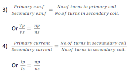
1) Primary e.m.f: The e.m.f of an alternating current connected to primary coil is called primary e.m.f
2) Secondary e.m.f: The e.m.f induced in the secondary coil is called secondary e.m.f
5) What is LORENTZ force?
A moving charge in magnetic field not parallel to the field experience a force called “LORENTZ FORCE” and since moving charge is called current then conductor carrying a current in magnetic field experiences
Force F = BIL in other words this force
F X B (Magnetic field)
F X I (current)
F X L (length of conductor inside the field)
S.I unit of magnetic field B = F /IT =N/Am = NA-1 m-1
Or unit is tesla (T)
IMPORTANT PROBLEMS & SOLUTIONS
1) A transformer lowers e.m.f from 220V to 15V. If the number of turns in primary is 3220, how many turns are in secondary coil?
Given: Ep = 220 V
Es = 15 V
NP = 3520, NS =?
Es / Ep =Ns/Np
15V/220V = Ns /3520
∴ NS = 3520x15V /220v = 240 𝑣
Number of turns in secondary coil are = 240 [ANS]
2) A transformer lowers e.m.f from 220V to 15 V. If 400 W power is given in primary.
Calculate:
1.The current in primary coil
2.The current in secondary coil
1.We know that Power = IP X EP
400 = IP X 220
∴ IP = 1.8A
So current in primary coil is 1.8A
2. IP X EP = Is X Es
∴IP X EP /Es
∴Is = 1.8 Χ 220 /15 =26.4A
3) In which position of coil is the magnitude of induced e.m.f
1. Maximum?
2. Minimum?
1.At 92° and 270°
2.At 180° and 360°

We hope you liked Electromagnetism ICSE Class 10 Physics Notes and solutions. If you have any questions please post them in the comments section below


