Question 1. (1) What do you understand by a simple machine?
(2) State the principle of an ideal machine.
Solution:
(1) A machine is a tool that allows us to increase speed or overcome a strong resistive force by exerting a modest force at a suitable location and in the desired direction.
(2) A perfect machine is one that has weightless and frictionless components, meaning that there is no energy loss of any kind. Its efficiency is 100 percent, meaning that the work input and output are equal.
Question 2. State four ways in which machines are useful to us?
Solution:
Machines are useful to us in the following ways:
(1) Using less effort to raise a big load.
(2) By shifting the effort’s application point to a useful location.
(3) By shifting the effort in a practical direction.
(4) To get a speed increase.
Question 3. Name a machine
(1) to multiply force ?
(2) to change the point of application of force ?
(3) to change the direction of force ?
(4) to obtain gain in speed ?
Solution:
(1) To multiply force: jack is used to raise a car.
(2) To change the point of application of force: The wheel of a bike is turned with the aid of a chain by exerting force to the pedal.
(3) To change the direction of force: A single fixed pulley is used to raise a bucket filled with water from the well by exerting downward force as opposed to upward force, which is used when the bucket is raised without the aid of a pulley.
(4) To obtain gain in speed: When a pair of scissors is used to cut fabric, the handles move very little while the blades travel longer on the fabric.
Question 4. What is the purpose of a jack in lifting a car by it?
Solution:
For jack to function as a force multiplier, the effort must be smaller than the load.
Question 5. (1) What do you understand by an ideal machine?
(2) How Does Ideal Machine Differ from a Practical Machine?
Solution:
(1) An ideal machine is one that has weightless and frictionless components, meaning that there is no energy loss of any kind. Its efficiency is 100 percent, meaning that the work input and output are equal.
(2)

Question 6. Explain the term mechanical advantage. State its unit.
Solution:
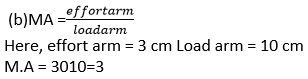
Machine mechanical advantage is defined as the load to effort ratio. It lacks a unit.
Question 7. Define the term velocity ratio, state its unit.
Solution:
The velocity ratio of a machine is the ratio of the velocity of effort to the velocity of the load. It lacks a unit.
Question 8. How is mechanical advantage related to the velocity ratio for an ideal machine?
Solution:
Mechanical advantage and velocity ratio are quantitatively equivalent for a perfect machine.
Question 9. (1) Define the term efficiency of a machine.
(2) Why is a machine not 100% efficient?
Solution:
(1) It is the proportion of the machine’s useful work to the effort’s work on the machine.
(2) The output energy is always less than the input energy in a real machine because of friction and the weight of the moving parts.
Question 10. When does a machine act as a
(1) force multiplier ?
(2) speed multiplier ?
(3) Can a machine act as a force multiplier and a speed multiplier simultaneously?
Solution:
(1) When the effort arm is longer than the load arm, a machine multiplies the force. Such devices have a mechanical advantage larger than 1.
(2) When the effort arm is shorter than the load arm, the machine operates as a speed multiplier. Such devices have a mechanical advantage that is less than 1.
(3) A machine cannot be both a force multiplier and a speed multiplier at the same time.
This is so that devices that increase force cannot also increase speed, and vice versa.
Question 11. A machine works as a
(i) force multiplier,
(ii) speed multiplier. In each case state whether the velocity ratio is more than or less than 1.
Solution:
(i) The displacement of load for a machine acting as a force multiplier is smaller than the displacement of effort. The velocity ratio is thus greater than 1.
(ii) The displacement of load is greater than the displacement of effort for a machine acting as a speed multiplier. The velocity ratio is thus smaller than 1.
Question 12. (i) State the relationship between mechanical advantage, velocity ratio and efficiency.
(ii) Name the term that will not change for a machine of a given design.
Solution:
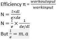
Efficiency multiplied by velocity ratio equals mechanical advantage.
M.A = η × V.R
The velocity ratio stays constant for a machine with a specific design.
Question 13. Derive the relationship between mechanical advantage, velocity ratio and efficiency of a machine.
Solution:
Let’s say that a machine uses an effort E to overcome a load L. Let dE represent the displacement of effort in time t and dL represent the displacement of load.
Work input = Effort × displacement of effort
Question 14. How is the mechanical advantage related with the velocity ratio for an actual machine? State whether the efficiency of such a machine is equal to 1, less than 1 or more than 1.
Solution:
The product of a machine’s efficiency and velocity ratio represents its mechanical advantage.
M.A. = V.R. × n
Such a machine’s efficiency is always less than 1, or h1. This is due to the constant loss of energy caused by friction and other factors.
Question 15. State reason why is mechanical advantage less than the velocity ratio for an actual machine.
Solution:
This is because energy is lost through friction since the output work is consistently less than the input work, resulting in an efficiency that is consistently lower than 1.
M.A = V.R × n
Question 16. (1) What is a lever?
(2) State the principle of a lever?
Solution:
(1) A stiff, straight or bent bar that can rotate along a fixed axis is referred to as a lever.
(2) Levers operate according to the idea of moments. It is thought that a perfect lever has no weight and no friction. According to the principle of moments, the moment of load about the fulcrum equals the moment of effort about the fulcrum when the lever is in its equilibrium position.
Load × Load arm = Effort × Effort arm.
Question 17. Write down a relation expressing the mechanical advantage of a lever.
Solution:

Question 18. Name the three classes of levers and distinguish between them. Give two examples of each class.
Solution:
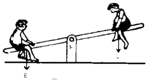
The three different types of levers are as follows: Examples include a crowbar, a seesaw, and some scissors.
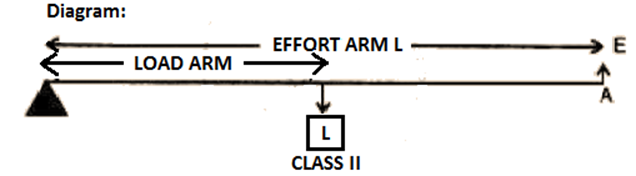
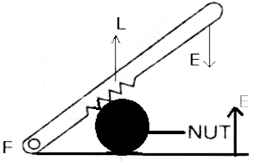
Levers in the Class II category place the load L between the E and F. Since the effort arm always exceeds the load arm, For instance, a bottle opener or a nutcracker.
The effort E in Class III levers is positioned between the fulcrum F and the load L, and the effort arm is always shorter than the load arm. Examples are using your forearm to lift a weight and sugar tongs.
Question 19. Give one example of a class I lever where
(1) Mechanical advantage is more than one?
(2) Mechanical advantage is less than one?
Solution:
(1) More than one: Multiple pairs of shears are employed to cut the thin metal sheets.
(2) Less than one: A pair of scissors with blades longer than their handles counts as less than one.
Question 20. What is the use of the lever if its mechanical advantage is
a. more than 1,
b. equal to 1, and
c. less than 1?
Solution:
The lever acts as a force multiplier when the mechanical advantage is greater than 1, allowing us to overcome a strong resistance with little effort.
(a) A lever has an equal-length effort arm and load arm when the mechanical advantage is 1.
(b) Levers are employed to increase speed when the mechanical advantage is less than 1. This suggests that there is a greater displacement of weight than there is of effort.
Question 21. A pair of scissors and a pair of pliers both belongs to the same class of levers. Name the class of lever. Which one has the mechanical advantage less than 1?
Solution:
Class I levers include both a set of scissors and a pair of pliers. The mechanical advantage of a pair of scissors is less than 1.
Question 22. Explain why scissors for cutting cloth may have blades longer than the handles, but shears for cutting metals have short blades and long handles.
Solution:
When cutting a piece of fabric, a pair of scissors has blades that are longer than the handles so that the movement at the handles is slower than the movement at the blades.
While metal-cutting shears have long handles and short blades because doing so allows us to easily overcome strong resistance.
Question 23. Shows a uniform metre scale of weight W supported on a fulcrum at the 60 cm mark by applying the effort E at the 90 cm mark.
(a) State with reason whether the weight W of the scale is greater than, less than or equal to the effort E.
(b) Find the mechanical advantage in an ideal case.

Solution:
(a) The uniform metre scale’s weight W activates at the 50 cm mark. The weight W of the scale is more than the effort E because the distance of the weight from the fulcrum F is smaller than that of the effort.
This is due to the arm being 30 cm on the side of effort E and 10 cm on the side of the scale’s weight. In order to maintain balance, the scale’s weight W should be greater than its effort E.
Question 24. Which type of lever has a mechanical advantage always more than one? Give one example. What change can be made in this lever to increase its mechanical advantage?
Solution:
There is usually more than one mechanical advantage with class II levers. For instance:- a nutcracker. We can lengthen the effort arm to boost its mechanical advantage.
Question 25. Draw a diagram of a lever which is always used as a force multiplier. How is the effort arm related to the load arm in such a lever?
Solution:
In such a lever, the effort arm is longer than the load arm.
Question 26. Explain why the mechanical advantage of a Class II type of lever is always more than 1.
Solution:
The load L in these levers is situated between the effort E and the fulcrum F. Since the effort arm always exceeds the load arm, As a result, M.A>1.
Question 27. Draw a labelled diagram of a class II lever. Give one example of such a lever.
Solution:

For instance:- a bottle opener.
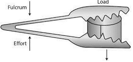
Question 28. Shows a lemon crusher.
1.) In the diagram, mark the position of the directions of load L and effort E.
(1) Name the class of lever.

Solution:
(1)

(2) The lever is of second-class.
Q29. The diagram below shows a rod lifting a stone.
(a) Mark position of fulcrum F and draw arrows to show the directions of load L and effort E.
(b) What class of lever is the rod?
(c) Give one more example of the same class of lever stated in part (b).

Solution:
(a)

b) Because the weight lies between the fulcrum and the effort, this rod is a class II lever.
c) A bottle opener is an illustration of a class II lever.
Question 30. State the kind of lever which always has the mechanical advantage less than
1. Draw a labeled diagram of such lever.
Solution:
Levers of class III usually have a negative mechanical advantage.

Question 31. Explain why the mechanical advantage of the class III type of lever is always less than 1.
Solution:
The effort arm in these kinds of levers is usually shorter than the load arm since it is located between the fulcrum F and the load L. Consequently, M.A. 1.
Question 32. Class III levers have mechanical advantage less than one. Why are they then used?
Solution:
With class III levers, we gain speed rather than force, which means that a larger displacement of load is achieved with a smaller displacement of effort.
Question 33. Draw a labeled sketch of a class III lever. Give one example of this kind of lever.
Solution:

Examples: foot treadle.
Question 34. State the class of levers and the relative positions of
(1) load (L) effort (E) and fulcrum (F) in a bottle opener?
(2) load (L) effort (E) and fulcrum (F) in sugar tongs.
Solution:
(1) It is given that the weight is in the middle, the fulcrum is at one end, and the effort is at the other, a bottle opener is a second-order lever.

(2) Because the effort is in the center, the weight is at one end, and the fulcrum is at the other, sugar tongs are a third-order lever.
Question 35. Draw Diagrams to illustrate the position of fulcrum load and effort, in the following :
(1) A seesaw
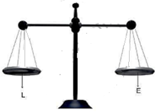
(2) A common balance.
(3) A nut cracker.
(4) Forceps.
Solution:
(1) A seesaw
(2) A common balance:
(3) A nut cracker:
(4) Forceps:

Question 36. Classify the following into lever as class I, class II or class III of a
(1) door
(2) catapult
(3) wheel barrow
(4) fishing rod
Solution:
(1) A door lever is Class II.
(2) A catapult lever is Class I.
(3) A wheel barrow lever is Class II.
(4) A fishing rod lever is Class III.
Question 37. What type of lever is formed by the human body while
(1) raising a load on the palm
(2) raising the weight of body on toes
Solution:
(1) Class III. The elbow of the human arm serves as the fulcrum here. The load on the palm is at the opposite end of the biceps’ center of effort.
(2) Class II. The load (i.e., the weight of the body) is in the middle, the fulcrum is at the toes at one end, and muscle exertion is at the other end.

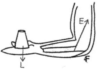
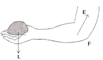
Question 38. Indicate the positions of load, effort and fulcrum in the forearm shown below in Fig 3.15 Name class of lever.

Solution:
It is Class III lever.
Question 39. Give example of each class of lever in a human body?
Solution:
(i) Class I lever in the head-nod action: In this action, the spine serves as the fulcrum, with load located at its front section and effort located at its back.
(ii) Class II lever for elevating body weight on toes: the load is in the middle, the muscle effort is at the other end, and the fulcrum is at the toes at one end.
(iii) Class III lever for elevating a weight with the forearm, with the load on the palm at one end, the elbow joint acting as the fulcrum in the center, and the biceps exerting the effort in the middle.
Question 40. Complete the following sentence:
(1) Mechanical advantage = ___________ × velocity ratio
(2) In class II lever, effort arm is __________ than the load arm.
(3) A scissors is a ___________ multiplier.
Solution:
(1) Mechanical advantage = efficiency × velocity ratio
(2) In class II lever, effort arm is greater than the load arm.
(3) A scissors is a speed multiplier.
Exercise – 3A
Multiple Choice Type:-
Question 1. Mechanical advantage (M.A), load (L) and effort (E) are related as :
a) M.A. = L x E
b) M.A. × E = L
c) E = M.A. × L
d) None of these
Solution: b) M.A. × E = L
Question 2. The correct relationship between the mechanical advantage (M.A), the velocity ratio (V.R) and the efficiency (n) is:
a) M.A. = η x V.R
b) V.R. = η x M.A.
c) η = M.A. x V.R.
d) None of these
Solution: a) M.A. = η × V.R
Question 3. State the incorrect statement:
a) A machine always has the efficiency less than 100%
b) The mechanical advantage of a machine can be less than 1.
c) A machine can be used as speed multiplier.
d) A machine can have the mechanical advantage greater than the velocity ratio.
Solution: It can have a mechanical advantage greater than the velocity ratio.
Reason: If the mechanical advantage of a machine is greater than its velocity ratio, then it would mean that the efficiency of a machine is more than 100%, which is practically not possible.
Question 4. The lever for which the mechanical advantage is less than 1 has:
a) Fulcrum at mid-point between load and effort.
b) Load between effort and fulcrum.
c) Effort between fulcrum and load.
d) Load and effort acting at the same point.
Solution: c) Effort is between fulcrum and load
Question 5. Class II levers are designed to have:
a) M.A. = V.R.
b) M.A. > V.R.
c) M.A. > 1
d) M.A. < 1
Solution: c) M.A > 1
Exercise-3A
Question 1. A crowbar of length 120 cm has its fulcrum situated at a distance of 20 cm from the load. Calculate the mechanical advantage of the crowbar.
Solution:
Crowbar’s overall length is 120 cm.
A load arm of 20 cm
Arm of effort: 120 – 20 = 100 cm
Calculation of Mechanical advantage

Question 2. A pair of scissors has its blades 15 cm long, while its handles are 7.5 cm long. What is its mechanical advantage?
Solution:
Arm of effort: 7.5 cm
Calculation of Mechanical advantage:-

Question 3. A force of 5 kgf is required to cut a metal sheet. A shears used for cutting the metal sheet has its blades 5 cm long, while its handles are 10 cm long. What effort is needed to cut the sheet?
Solution:
Arm of effort = 10 cm
Question 4. Fig 3.16 below shows a lever in use.

(a) To which class of lever does it belong?
(b) If AB = 1m, AF = 0.4 m, find its mechanical advantage,
(c) calculate the value of E.
Solution:
(a) This is a class I lever.
(b) Assuming AB = 1 m, AF = 0.4 m, and BF = 0.6 m
Calculation of Mechanical advantage
M.A. = 𝐵𝐹×𝐴𝐹
M.A. = 0.60×4
M.A. = 1.5
(c) Load = 15kfg
Effort = load/ma
Effort = 15/1.5
Effort = 10kgf
Question 5. A man uses a crowbar of length 1.5 m to raise a load of 75 kgf by putting a sharp edge below the bar at a distance 1 m from his hand. Draw a diagram of the arrangement showing the fulcrum (F), load (L) and effort (E) with their directions. State the kind of lever. Calculate:
(1) load arm,
(2) effort arm,
(3) mechanical advantage and
(4) the effort needed.
Solution:
Crowbar is a class I lever.
(1) Total length of crowbar = 1.5m
Effort arm = 1 m
Load arm = 1.5-1 = 0.5 m
(2) Effort arm = 1m

Question 6. A pair of scissors is used to cut a piece of a cloth by keeping it at a distance 8.0 cm from its rivet and applying an effort of 10 kgf by fingers at a distance 2.0 cm from the rivet.
(a) Find: (i) the mechanical advantage of scissors and
(ii) the load offered by the cloth
(b) How does the pair of scissors act: as a force multiplier or as speed multiplier?
Solution:
(a) Effort arm = 2 cm Load arm = 8.0 cm Given effort =10kgf
(i) Calculation of Mechanical advantage

M.A. =0.25
(ii) Load = M.A × effort
Load = 0.25 × 10
Load = 2.5 kgf
(b) The pair of scissors acts as a speed multiplier because MA < 1.
Question 7. A 4 m long rod of negligible weight is to be balanced about a point 125 cm from one end. A load of 18 kgf is suspended at a point 60 cm from the support on the shorter arm.
(a) a weight W is placed 250 cm from the support on the longer arm Find W.
(b) If W = 5 kgf, where must it be kept to balance the rod?
(c) To which class of lever does it belong?
Solution:
Total length of rod = 4m = 400 cm
(a) 18kgf load is placed at 60 cm from the support. W kgf weight is placed at 250 cm from the support.
According to the principle of moments
= 18 × 60
= W × 250W
= 4.32 kgf
(b) Given W = 5kgf
18kgf load is placed at 60 cm from the support.
Let us assumed that 5 kgf of weight is placed at d cm from the support.
According to the principle of moments
18 × 60 = 5 x d
d = 216 cm from the support on the longer arm
(c) It belongs to class I lever.
Question 8. A lever of length 9 cm has its load arm 5 cm long and the effort arm is 9 cm long.
(1) To which class does it belong
(2) Draw diagram of the lever showing the position of fulcrum F and directions of both the load L and effort E.
(3) What is the mechanical advantage and velocity ratio if the efficiency is 100%?
(4) What will be the mechanical advantage and velocity ratio if the efficiency becomes 50%?
Solution:
(1) The lever’s length corresponds to the effort arm’s length. Additionally, effort arm is greater than load arm. So, this is a class II lever.
(2) Diagram of the lever showing the position of fulcrum F and directions of both the load L and effort E.

(3) Calculation of Mechanical advantage is

Relation between MA, efficiency and V.R. is
M.A. = η × V.R.
M.A. = V.R. = 1.8 (η = 100 % = 1)
(4) When efficiency reduces, its mechanical advantage reduces and velocity ratio remains the same. So, when efficiency becomes 50%, M.A. = 0.9 and V.R. = 1.8
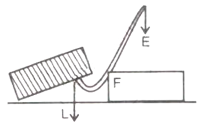
Question 9. Fig 3.17 below shows a lever in use.

(a) To which class of lever does it belong?
(b) If FA = 80 cm, AB = 20 cm, find its mechanical advantage.
(c) Calculate the value of E.
Solution:
(a) This is a class II lever.
(b) Given: FA=80 cm, AB = 20 cm, BF= FA+AB=100cm
Calculation of Mechanical advantage
Question 10. Fig 3.19 below shows a wheel barrow of mass 15 kg carrying a load of 30 kgf with its centre of gravity at A. The points B and C are the centre of wheel and tip of the handle such that the horizontal distance AB = 20 cm and AC = 40 cm.

Calculate:
(i) the load arm,
(ii) the effort arm,
(iii) the mechanical advantage and
(iv) the minimum effort required to keep the leg off the ground.
Solution:
(i) Load arm AF = 20 cm
(ii) Effort arm CF = 60 cm
(iii) Calculation of Mechanical advantage

Question 11. Fig 3.18 below shows the use of a lever.

(a) State the principle of moments as applied to the above lever.
(b) Give an example of this class of lever.
(c) If FA = 10 cm, AB = 500 cm calculate:
(i) the mechanical advantage and
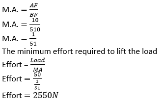
(ii) the minimum effort required to lift the load.
Solution:
(a) The momentary principle Moment of effort about fulcrum = moment of load about fulcrum
(b) FB × Load = FA × Effort
(c) Sugar tongs the example of this class of lever.
(d) Given: FA = 10 cm, AB = 500 cm,
BF = 500 + 10
BF = 510 cm.
Calculation of Mechanical Advantage
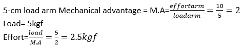
Question 12. A fire tongs has arms 20 cm long. Its is used to lift a coal of weight 1.5 kgf by applying an effort at a distance 15 cm from the fulcrum. Find:
(i) the mechanical advantage of fire tongs and
(ii) the effort needed
Solution:
Fire tongs has its arms =20 cm Effort arm = 15 cm Load arm =20 cm

Exercise-3B
Question 1. What is a single fixed pulley? State its one use.
Solution:
A pulley is referred to as a fixed pulley if its axis of rotation is fixed in place. Lifting a little weight from the well, such as a pail of water, requires only one fixed pulley.
Question 2. What is the ideal mechanical advantage of a single fixed pulley? Can it be used as a force multiplier?
Solution:
A single fixed pulley’s optimal mechanical advantage is 1, and thus cannot be utilized as a force multiplier.
Question 3. Name the pulley which has no gain in mechanical advantage. Explain, why is such a pulley then used?
Solution:
A single fixed pulley’s optimal mechanical advantage is 1, and thus cannot be utilized as a force multiplier.
Question 4. What is the velocity ratio of a single fixed pulley?
Solution:
One fixed pulley has a single velocity ratio of 1.
Question 5. In a single fixed pulley, if the effort moves by a distance x downwards, by what height is the load raised upwards?
Solution:
The burden ascends by the same amount (x).
Question 6. What is a single movable pulley? What is its mechanical advantage in the ideal case?
Solution:
A pulley is referred to as a single movable pulley if its axis of rotation is not fixed in place. In the ideal scenario, mechanical advantage is 2.
Question 7. Name the type of single pulley that can act as a force multiplier. Draw a labelled diagram of the pulley mentioned by you.
Solution:
A single moving pulley may double the force.

Question 8. Give two reasons why the efficiency of a single movable pulley system is not 100%?
Solution:
Because of these factors, a single moveable pulley system’s efficiency is not 100%.
(i) The pulley bearing’s friction is not zero,
(ii) The pulley and string do not have a weight of zero.
Question 9. In which direction does the force need to applied when a single pulley is used with a mechanical advantage greater than one? How can you change the direction of force applied without altering its mechanical advantage? Draw a labeled diagram of the system.
Solution:
The force should be in an upward direction. The direction of force applied can be changed without altering its mechanical advantage by using a single movable pulley along with a single fixed pulley to change the direction of applied force.
Question 10. What is the velocity ratio of a single movable pulley? How does the friction in the pulley bearing affect it?
Solution:
A single moveable pulley’s velocity ratio is always 2.
Question 11. In a single movable pulley, if the effort moves by a distance x upwards, by what height is the load raised?
Solution:
The weight is increased to x/2 height.
Question 12. Draw a labeled diagram of an arrangement of two pulleys, one fixed and other movable. In the diagram, mark the directions of al forces acting on it. What is the ideal mechanical advantage of the system? How can it be achieved
Solution:
The system’s ideal mechanical advantage is 2. This may be accomplished by assuming that the pulley and the string are massless and that there is no friction between the string and the pulley’s rim, the axle, or the bearings on the pulley.
Question 13. The diagram below shows a pulley arrangement.
(a) In the diagram, mark the direction of tension on each strand of string.
(b) What is the purpose of the pulley B? (c) If the tension is T, Deduce the relation between T and E.
(d) What is the velocity ratio of the arrangement?
(e) Assuming that the efficiency of the system is 100%, What is the mechanical advantage?
Solution:
(a)
(b) The fixed pulley B is utilized to switch the required zz upward to a downward direction.
(c) The tension T at the free end is balanced by the effort E, hence E=T
(d) This configuration has a velocity ratio of 2.
(e) This system has a mechanical advantage of 2. (if efficiency is 100 percent ).
Question 14. Differentiate between a single fixed pulley and a single movable pulley.
Solution:

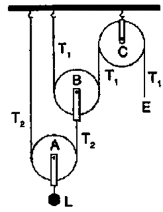
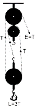
Question 15. The Diagram alongside shows an arrangement of three pulleys A, B, and C. The load is marked as L and the effort as E.
(a) Name the Pulleys A, B, and C.
(b) Mark in the diagram the directions of load (L), effort (E) and tension T1 and T2 in the two strings.
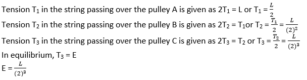
(c) How are the magnitudes of L and E related to the tension T1?
(d) Calculate the mechanical advantage and velocity ratio of the arrangement.
(e) What assumptions have you made in parts (c) and (d)?
Solution:
(a) The pulleys A and B can be moved. The fixed pulley is pulley C.
(b)

(c) The magnitude of effort E = T1 and the magnitude of L = 22 T1 = 4 T1
(d) The mechanical advantage = 22 = 4
The velocity ratio = 22 = 4
(e) Weightlessness of pulleys A and B is assumed.
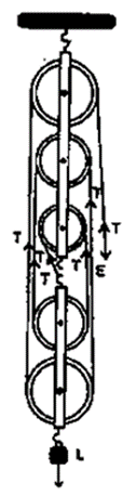
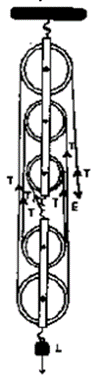
Question 16. Draw a diagram of combination of three movable pulleys with a fixed pulley showing the directions of load, effort and tension in each strand. Find:
(i) mechanical advantage,
(ii) Velocity ration and
(iii) Efficiency of the combination in ideal situation.
Solution:
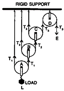
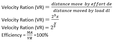
Calculation of Mechanical advantage = M.A. = 23
As one end of each string passing over a movable pulley is fixed, so the free end of string moves twice the distance moved by the movable pulley. If load L moves up by a distance x, dL = x, effort moves by a distance 23 xde = 23 x
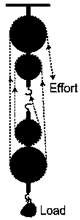
Question 17. A block and tackle pulley system has a velocity ratio 5. Draw a labelled diagram of this system. In your diagram, indicate clearly the points of application and the directions of the load and effort.
Solution:
Question 18. Give a reason for the following:
(1) In a single fixed pulley, the velocity ratio is always more than the mechanical advantage.
(2) The efficiency of a movable pulley is always less than 100%.
(3) In the case of a block and tackle arrangement, the mechanical advantage increases with the increase in the number of pulleys.
(4) The lower block of a block and tackle pulley system must be of negligible weight
Solution:
(1) The effort required to overcome friction between the strings and the pulley grooves in a single fixed pulley is larger than the load, hence the mechanical advantage is smaller than the velocity ratio.
(2) The effort needed to overcome friction between the strings and the pulley grooves in a single fixed pulley is more than the load, hence the mechanical advantage is smaller than the velocity ratio.
(3) This is so because the total number of pulleys in both blocks equals the mechanical advantage.
(4) This is so because the total number of pulleys in both blocks equals mechanical advantage.
Question 19. Name a machine which is used to :
(1) Multiply force
(2) Multiply speed
(3) Change the direction for force applied.
Solution:
(1) To increase force: an automobile is lifted using a jack.
(2) Gear system or class III lever for speed multiplication.
(3) Use a single fixed pulley to reverse the direction of applied force.
Question 20. State whether the following statement is true or false:
(1) The velocity ratio of a single fixed pulley is always more than 1.
a) True
b) False
Solution: False
(2) The velocity ratio of a single movable pulley is always 2.
a) True
b) False
Solution: True
(3) The velocity ratio of a combination of n movable pulleys with a fixed pulley is always 2n
a) True
b) False
Solution: True
(4) The velocity ratio of a block and tackle system is always equal to the number of strands of the tackle supporting the load.
a) True
b) False
Solution: True
Exercise-3B
Multiple Choice Type:-
Question 1. A Single fixed pulley is used because it:
a) Has a mechanical advantage greater than 1
b) Has a velocity ratio less than 1
c) Gives 100% efficiency
d) Helps to apply the effort in a convenient direction.
Solution: d) helps in applying effort in a convenient direction.
Question 2. The mechanical advantage of an ideal single movable pulley is
a) 1
b) 2
c) less than 2
d) less than 1
Solution: b) 2
Question 3. A movable pulley is used as:
a) a force multiplier
b) a speed multiplier
c) a device to change the direction of effort
d) an energy multiplier
Solution: a) a Force multiplier
Exercise-3B
Question 1. A Woman draws water from a well using a fixed pulley. The mass of bucket and water together is 6 kg. The force applied by the woman is 70 N. Calculate the mechanical advantage. (Take g = 10 m s-2)
Solution:
The force applied by the women is = 70 N.
The mass of bucket and water together is = 6 kg
Total load = 6 × 10
Total load = 60N
Calculation of Mechanical advantage

Question 2. A fixed pulley is driven by a 100 kg mass falling at a rate of 8.0 m in 4.0s. It lifts a load of 75.0 kgf. Calculate
(1) The power input to the pulley taking the force of gravity on 1 kg as 10 N.
(2) The efficiency of the pulley.
(3) The height to which the load is raised in 4.0 s.
Solution:
(1) Load = 75.0 kgf
Mass of falling object = 100 kg
Displacement of effort = 8.0 m
Time taken = 4.0s
Effort = 100 X 10 = 1000 kgf
Power Input

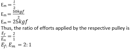
Question 3. A single fixed pulley and a movable pulley both are separately used to lift a load of 50 kgf to the same height. Compare the efforts applied.
Solution:
In case of a single fixed pulley, the effort (Ef needed to lift a load) is equal to the load itself.
Thus, Ef = L
In case of a single movable pulley, the effort needed to lift a load is equal to half the load.
Question 4. In a block and tackle system consisting of 3 pulleys, a load of 75 kgf is raised with an effort of 25 kgf. Find
(i) The mechanical advantage
(ii) Velocity ratio and
(iii) Efficiency.
Solution:
Load = 75 kgf
Effort = 25 kgf
n = 3

Question 5. A block and tackle system has 5 pulleys. If an effort 0f 1000 N is needed in the downward direction to raise a load of 4500 N, calculate:
(a) the mechanical advantage
(b) the velocity ratio, and
(c) the efficiency of the system
Solution:
A block and tackle system has 5 pulleys. (n = 5) Effort = 1000N Load = 4500 N

Question 6. In following figure , draw a tackle to lift the load by applying the force in the downward direction. Mark the position of load and effort.
(a) If the load is raised by 1 m, through what distance will the effort move?
(b) State how many strands of tackle are supporting the load?
(c) What is the mechanical advantage of the system?

Solution:
(a) The effort move = 1 × 5 = 5m
(b) Five strands of tackle are supporting the load.
(c) Calculation of Mechanical advantage of the system

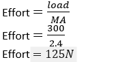
Question 7. A pulley system has a velocity ratio 3 and an efficiency of 80%. Draw a labeled diagram of this pulley system Calculate:
(a) the mechanical advantage of the system and
(b) the effort required to raise a load of 300 N.
Solution:
A pulley system has a velocity ratio = 3 Efficiency of system = 80 % = 0.8
Calculation of Mechanical advantage of the system
M.A = V.A × η = 3 × 0.8 = 2.4
Calculation of Effort required raising the load
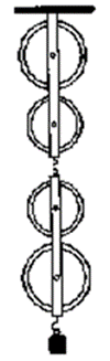
Question 8. In following figure , shows a system of four pulleys, The upper two pulleys are fixed and the lower two are movable.
(a) Draw a string around the pulleys. Also show the place and direction in which the effort if applied.
(b) What is the velocity ratio of the system?
(c) How are load and effort of the pulley system related?
(d) What assumption do you make in arriving at your answer in part (c)?
Solution:
(a)
(b) Velocity ratio of the system = n = 4
(c) The relation between load and effort M.A. = load/effort = n = 4
(d) (i) The pulley bearing has no friction.
(ii) Lower pulleys’ weight is little, and
(iii) The effort is directed downward.
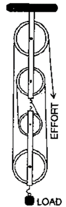
Question 9. In following figure, shows a block and tackle system of pulleys used to lift a load.
(a) How many strands of tackle are supporting the load?
(b) Draw arrows to represent tension in each strand.
(c) What is the mechanical advantage of the system?
(d) When load is pulled up be a distance 1 m, how far does the effort end move?
Solution:
(a) There are 4 strands of tackle supporting the load.
(b)

(c) Calculation of Mechanical Advantage of the system
M.A. = load/effort
M.A. = 4T/T
M.A. = 4
(d) When load is pulled up by a distance 1m.
The effort end will move by a distance = 1 x 4 = 4m.
Question 10. A block and tackle system has the velocity ratio 3. Draw a labeled diagram of the system indicating the points of application and the directions of load and effort. A man can exert a pull of 200 kgf.
(1) What is the maximum load he can raise with this pulley system is its efficiency is 60%?
(2) If the effort end moves a distance 60 cm, what distance does the load move
Solution:
A block and tackle system has the velocity ratio = 3 i.e., VR = n = 3
Efficiency of system η = 60% = 0.6 The mechanical advantage of the system MA. = V.A × η = 3 × 0.6 = 1.8 Man can exert a maximum effort = 200 kgf
Load = M.A. × effort = 1.8 × 200 = 360 kgf
(2) For block and tackle system, V.R. = n (number of pulleys)
Hence, n = 3
The diagram is as shown below

The velocity ratio of system is V.R. = 3
Hence, we get
Question 11. You are given four pulleys and three strings. Draw a neat and labeled diagram to use them so as to obtain a maximum mechanical advantage equal to 8. In you diagram make the directions of load, effort and tension in each strand. What assumptions have you made to obtain the required mechanical advantage?

Solution:
Below are the assumptions:-
(i) The pulley bearing has no friction.
(ii) The pulleys and the string have no mass.