Students should refer to Machines ICSE Class 10 Physics notes provided below designed based on the latest syllabus and examination pattern issued by ICSE. These revision notes are really useful and will help you to learn all the important and difficult topics. These notes will also be very useful if you use them to revise just before your Physics Exams. Refer to more ICSE Class 10 Physics Notes for better preparation.
ICSE Class 10 Physics Machines Revision Notes
Students can refer to the quick revision notes prepared for Chapter Machines in Class 10 ICSE. These notes will be really helpful for the students giving the Physics exam in ICSE Class 10. Our teachers have prepared these concept notes based on the latest ICSE syllabus and ICSE books issued for the current academic year. Please refer to Chapter wise notes for ICSE Class 10 Physics provided on our website.
Machines ICSE Class 10 Physics
Simple Machines and Terminologies
A machine is a device through which we can either overcome a large resistive force present at some point by applying a small force at a specific point in a desired direction or obtain a gain in speed.
These machines have been used for centuries not only to make work easy, but also to make it efficient and safe. As the name suggests, the construction of simple machines are not complicated and they are used for day-to-day simple works. The other characteristic feature of simple machines is that they do not convert energy from one form to another. Complicated machines such as bicycles and screwing machines are made up by combining two or more simple machines.
Simple machines can be broadly classified into two categories.
• Lever
• Inclined plane
These two types are further divided into sub-categories, as shown in the given diagram.

A lever is a rod which moves freely about a fixed point called the fulcrum.
Parts of a Lever

Levers are of three types depending on the position of the fulcrum, load and effort.
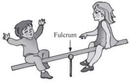
Lever of first order: Fulcrum is situated between the load and the effort. E.g., see-saw, crowbar, beam balance’

Lever of second order: Load is situated between the fulcrum and the effort. E.g., mango-cutter, wheel barrow, nut cracker

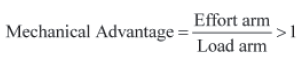
Lever of third order: Effort is situated between load and the fulcrum. E.g, pair of tongs, fishing rod

An inclined plane provides a sloping surface over which heavy things can easily be lifted or rolled down.

There are certain common terms that are used for almost every simple machine. Let us understand these terminologies first.
Machine Terminology
• Effort — The force applied to a machine to do mechanical work is called effort.
• Load — The force applied on an object by the machine is called load. When a crow bar is used for lifting an object, the weight of the object is the load, as that is the amount of force the simple machine has to apply to lift the object.
• Fulcrum — When a machine does mechanical work by turning on a point, the point of rotation is called the fulcrum. In the given picture, the middle point is the fulcrum of the seesaw.
• Input Energy — The work done on a machine or the energy supplied to a machine is called input energy.
• Output Energy — It is the work done by the machine or the energy obtained from the machine.
• Principle of Ideal Machine — In an ideal machine, the output energy is equal to the input energy. Therefore, mathematically we can express it as input = output. This is called the principle of machine.
• Mechanical Advantage— It is the ratio of the force obtained from the machine to that applied to the machine. In simple words, we can say Mechanical Advantage = Load / Effort
• Velocity Ratio— It is defined as the ratio of the displacement of effort to the displacement of load.

• Efficiency — The ratio of the energy obtained from the machine to that supplied to it is known as the efficiency of the machine. It is obtained by dividing the amount of work done by the machine by the work done on the machine.

• In an ideal machine, all the input energy is converted into output energy i.e., the efficiency of an ideal machine is 100%. In real life, no machine can have 100% efficiency because some amount of input energy always gets lost to overcome the friction between the different parts of the machine.
• Relation Between Mechanical Advantage (M.A.) and Velocity Ratio (V.R.): Assume a machine is doing a work in time t to overcome a load L by the application of effort E. Let the displacement of effort be dE and of load be dL.

where, ηη is the efficiency the machine.
We must take care of machines to minimize its wear and tear. We can take care ofmachines by:
• Keeping them away from dust and moisture
• Lubricating them properly
• Painting iron parts
Levers
A lever is a simple machine. It consists of a rigid bar, which is capable of turning around a pivot, which is also called a fulcrum. Generally, we use a rod, which can rotate freely about the fulcrum.

For lever, we generally use two more terms apart from the general terms used for all the machines.
• Load Arm— It is the distance between the fulcrum and the point where the load is applied.
• Effort Arm — It is the distance between the fulcrum and the point where the effort is put.

The working of all levers is based on a common principle, which is called principle of lever.
Principle of lever
Load × Load arm = Effort × Effort arm
If we rearrange the equation, we obtain

Therefore, the mechanical advantage of a lever is nothing but the ratio of the length of its effort arm to the load arm.
Different Types of Lever
Levers are classified into three types depending upon the positions of load, fulcrum, and effort.
Lever of first order
When the fulcrum is situated between load and effort, we call it a lever of first order. For example, beam balance, a crowbar, a seesaw.


Mechanical advantage of a lever of first order
In case of First order lever Mechanical advantage can be equal to 1 or greater than or less than 1.It depends on the position of the fulcrum between effort arm and load arm. In case of levers of first order, we try to keep the load arm smaller than the effort arm i.e., effort arm > load arm. Therefore, a big load can be shifted by using small effort with the help of a lever of first order. As the effort arm is larger than the load arm,
When effort arm is less than load arm then mechanical advantage is less than 1.When Effort arm is equal to load arm then mechanical advantage is equal to 1.
Lever of second order
When the fulcrum and effort are situated at the two opposite ends of the lever and a load is placed in between them, we call it a lever of second order. For example, a nutcracker, a wheel-barrow, etc.


Mechanical advantage of a lever of second order
In case of levers of second order, the load arm is always smaller than the effort arm i.e., effort arm > load arm. Therefore, a big load can be shifted by using small effort with the help of a lever of second order. As the load arm is larger than the effort arm,

Lever of third order
When the fulcrum and load is situated at the opposite ends of the lever and an effort is applied somewhere between them, we call it a lever of third order. For example, a pair of tongs, a fishing rod, etc.
Mechanical advantage of a lever of third order
In case of levers of third order, the effort arm is always smaller than the load arm i.e., load arm > effort arm. As the load arm is larger than the effort arm,

Although we do not obtain mechanical advantage from a lever of third order, we use it for several reasons.
• We use lever of third order where other two kinds of lever cannot be used.
• In case of lever of third order, we always obtain bigger displacement of load by the minimum displacement of the applied force. That is why we use a lever of third order in fishing rod.
Order of Levers found in Human Body
(1) First order lever: Nodding of head
(2) Second order lever: Raising the weight of the body on toes
(3) Third order lever: Raising a load by forearm
Can you say why we use a fire tong or tweezers although we do not get any mechanical advantages from them?
Pulley and Wheel–Axle
Pulley

Nisha goes to her native village. There she sees women lifting water from a well. She notices that the rope, by which the women are drawing the water bucket, passes over a circular disc. Do you know why the circular disc is used?
The wheel has a groove on it. This keeps the rope passing over it from slipping. This rope is, in turn, tied to a bucket. Now, when the rope is pulled downwards, the rotation of the wheel brings the bucket upwards.
The whole arrangement is called pulley system. A pulley system is used for lifting heavy loads easily.
Do you know why we use pulley system to lift heavy load?
It is sometimes easier to apply force in one direction than the other. For example, it is always easier to apply force in the downward direction than in the upward direction. The primary purpose of a pulley is to change the direction of the force. It is made up of a circular disc or a wheel, which can rotate about a fixed axis that passes through its centre. The disc has a groove in its edge to provide better grip to the rope passed over it.

You must have seen at any construction site that large cranes have a pulley system fixed at the top of their long arms and some ropes are passed over them to lift heavy loads.
Mechanical Advantage of pulley
The effort applied is equal to the load to be lifted in case of an ideal pulley.

Whereas the mechanical advantage is less than 1 in case of an actual pulley which means that the effort is more than the load.
Wheel−Axle
As the name suggests, wheel and axle comprise of a wheel and a rod (axle) passes through the centre of the wheel. The wheel is attached to the rod in such a way that when we turn the wheel, the axle also turns. Let us take the example of a screw driver, which is a wheel and axle. The handle of the screw driver is the wheel and the rod is the axle. When we turn the wheel, the rod also turns. Screw driver always uses lesser force because the long handle gives more space to apply it. Other examples of wheel and axle are door knob, steering wheel of a car, etc.

You can also use wheel−axle to take water out from a well. In that case, two separate ropes are passed over the wheel and the axle, but the ropes are whirled in opposite turns. The bucket is attached to the rope that passes over the axle. To take water out of the well, you have to pull the rope whirled around the wheel. This, in turn, rotates the axle and the rope attached to it whirls around it. In this way, the water-filled bucket comes up.

Block and Tackle System
Movable pulley
A pulley whose axis of rotation is movable is called a movable pulley.

In a single movable pulley, an inextensible string of negligible mass passes around the grooved rim of the pulley. A load L which is to be raised by applying an effort E is suspended from the axle of the pulley. One end of the string is fixed to the hook at a rigid support and the other free end is used for applying the effort E. Tension T is acting on the string on both sides of the pulley.
Mechanical advantage (M.A.), Velocity ratio (V.R.) and Efficiency (ηη) of single movable pulley:
Assumptions:
(1) Friction free pulley bearings or axle
(2) Negligible weight of pulley and string
The load is getting balanced by the tension in each segment of the string and the effort balances the tension at the free end of the string as is shown in the above figure.
So,
L = 2T and E = T
⇒⇒ E = L/2
Hence, single movable pulley acts as a force multiplier as effort required to lift the load is half of the load.

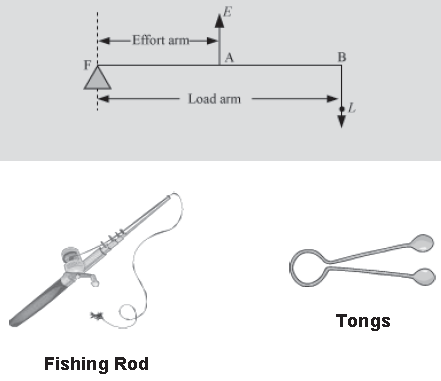
Now, when effort E pulls the free end of the string through a distance of 2d, the load only moves up by a distance of d. This is because the segment of string on both sides of the pulley moves up a distance d. Therefore,
However, in the actual scenario, the efficiency is less than 100% because in real friction there is always there in pulley’s ball bearings or at the axle and even the pulley and the string has some weight.
If you notice in case of a single movable pulley, the effort has to be applied in the upward direction which is very inconvenient. To overcome this, a new arrangement is made in which this movable pulley is paired with a fixed pulley so as to change the direction of effort from upward (as in the single movable pulley) to downward. However, the mechanical advantage (M.A.), velocity ratio (V.R) and efficiency (ηη) of this arrangement or system are same as that of single movable pulley.
To lift heavy loads or to shift them from one place to another, we require mechanical advantage more than 2. Thus, this makes the single movable pulley or the movable and fixed pulley system not appropriate for lifting and shifting of heavy loads as their mechanical advantage is less than 2. To perform such heavy task, we
need combination of several pulleys which can provide us mechanical advantage greater than 2. Two such systems are:
(1) System with one fixed pulley and several movable pulleys attached to a same rigid support

In the above system, pulleys A, B and C are movable and D is fixed. When this system is in equilibrium position, its effort is
E = T3 ….(1)
Load L is supported by the two segments of the string passing over the pulley A. Thus,

Similarly, at pulley B, two segments of string support the tension T1. Thus,

So, the mechanical advantage for a system having 3 movable pulleys with on fixed pulley is 23. This means that if there are n movable pulleys with one fixed pulley, then the mechanical advantage of such system is 2n .
Velocity ratio (V.R.)
Here, one end of each of the string passing over a movable pulley is fixed, thus its other end moves up twice the distance moved by the axle of the movable pulley.

And in general, we say velocity ratio is 2n when n is the number of movable pulleys in the system.

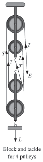
It is a system in which two separate blocks, consisting several pulleys, are arranged in such a way that one is above the other. The upper block is attached to a rigid support and is thus fixed and the other block (lower) is movable. The number of movable pulleys in the lower block is less than or equal to the number of pulleys in the fixed upper block.
A strong and inextensible string of negligible mass passes around all the pulleys. One end of this string is attached to the hook of the lower block (if number of pulleys in upper block > number of pulleys in upper block) or it is attached to the hook of the upper block (if number of pulleys in upper block = number of pulleys in upper block) so as to apply
the effort in the downward direction.

Above figure shows a block and tackle system in which 3 pulleys and 2 pulleys are used in the upper block and lower block, respectively. The one end of the string is attached to the hook of the lower block (as number of pulleys in upper block (3) > number of pulleys in upper block (2)).
Also, load L is attached to movable lower block and effort E is applied at the free end of the string. As soon as the load is hanged, a tension T is produced in the string along its entire length.
Let’s find its mechanical advantage (M.A) which is the ratio of load and effort. As the tension in the five segments of string supports the load, so the total load equals to five times of the tension in the each segment of the string (L = 5T) and effort is equals to tension T (E=T). Thus,
M. A. = L / T = 5T / T = 5 ….. (1)
Consider one more block and tackle system in which each of the two blocks, upper and lower, consist two pulleys.
To find the mechanical advantage of this system, we go by the similar approach as discussed above. The tension in the four segments of string supports the load L at the lower end of the block. Thus, L = 4T and effort is equal to tension T i.e. E=T.
M. A. = L / T = 4T / T = 5 ….. (1)
So, in general we can say that if the total number of pulleys used in upper and lower block is n and the effort applied is in the downward direction, then the tension in the n segments of the string supports the load L. Thus
L = nT and E = T
⇒ E = L / n ….. (3)
Using equation (3), we got to know that the effort required to balance the load is the ratio of load (L) to the number of pulleys (n) in the block and tackle system. Therefore, in the said system the effort is n times the load, where n is the total number of pulleys in the given blocks. Hence, block and tackle system acts as a force multiplier. This means mechanical advantage of block and tackle system is equal to the total number of pulleys in both the block.

Velocity ratio (V.R.)
In a block and tackle system of n pulleys, if the load is moved by a distance d, each segment of the string supporting the load is loosened by a length d. Thus, the distance moved at the effort end is nd.

Efficiency is 100% as M.A. and V.R. are equal.
Effect of the weight of pulleys on mechanical advantage (M.A.), velocity ratio (V.R.) and efficiency (ηη)
Suppose a system of n pulleys having was the weight of the lower block along with the pulleys in it. So, in equilibrium position

From the above equation, we figure out that the mechanical advantage is less than the ideal value n.
The velocity ratio does not change; it remains the same. However, efficiency will change because M.A. changes.

From the above relation of efficiency, we see that efficiency increases if the pulleys in the lower block are made as light as possible.


