Exercise-10A
Question 1. Describe an experiment to demonstrate that there is a magnetic field around a current-carrying conductor.
Solution:
In Fig., AB is represented as a wire that runs from north to south and is linked to a battery via a rheostat and a tapping key. The wire is positioned right below a compass needle.
(1) The needle does not deflect and points in the N-S direction (i.e., along the earth’s magnetic field) while the key is open, i.e., no current flows through the wire. As seen in Fig., the needle is parallel to the wire in this position (a).

(a) When a key is open, the needle showed no deflection and it point in the N S direction.
(2) Upon depressing the key, a current flows through the wire in the direction of A to B (i.e., from south to north), causing the needle’s North Pole (N) to deflect in the direction of the west
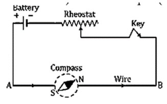
(b) When the key is, pressed, the nether pole (N) of the needle deflects towards the west.
(3) The needle’s North Pole (N) deflects toward the east when the direction of current in the wire is switched by switching the connections at the battery terminals [Fig. (c)].

(c) When the direction of current in the wire is reversed, the North Pole (N) of the needle deflects towards the east.

(d) If the compass needle is placed just above the wire, the North Pole (N) deflects towards east when the direction of current in wire is from A to B.
(4) When the direction of the current in the wire is from A to B [Fig. (d)], the North Pole (N) deflects towards the east; but, if the direction of the current in the wire is from B to A, the
Needle deflects towards the west as shown in Fig. (e).

(e) If the compass needle is held directly above the wire and the wire’s current is flowing from B to A, the needle will deflect toward the west. According to the experiment’s aforementioned findings, a current-carrying wire generates a magnetic field all around it.
Question 2. Draw a diagram showing the directions of three magnetic field lines due to a straight wire carrying current. Also show the direction of current in the wire.
Solution:

Question 3. How is the magnetic field due to a straight current carrying wire affected if (i) current in wire is decreased?
(ii) Current in wire is reversed?
Solution:
(i) As the current is reduced, fewer magnetic field lines exist.
(ii) Magnetic field lines will change their direction.
Question 4. State a law, which determines the direction of magnetic field around a current carrying wire.
Solution:
The magnetic field direction surrounding a current-carrying wire is determined using the righthand thumb rule. According to this, if we hold the current-carrying conductor in our right hand with our thumb pointing in the direction of the current, our fingers should be wrapped around the wire in the direction of the lines of the magnetic fields.
Question 5. A straight wire lying in a horizontal plane carries a current from north to south. (a) What will be the direction of magnetic field at a point just underneath it? (b) Name the law used to arrive at the answer in part (a).
Solution:
(a) A location immediately below has a magnetic field that points east.
(b) Right-hand rule of thumb.
Question 6. What will happen to a compass needle when the compass is placed below a wire and a current is made to flow through the wire? Give a reason to justify your answer.
Solution:
The magnetic needle in a magnetic field created by a current-carrying conductor experiences a torque that causes it to deflect in order to align itself with the magnetic field’s direction.
Question 7. Draw a labeled diagram showing the three magnetic field lines of a loop carrying current. Mark the direction of current and the direction of magnetic field by arrows in your diagram.
Solution:

Question 8. A wire, bent into a circle, carries current in an anticlockwise direction. What polarity does this face of the coil exhibit?
Solution:
North polarity is visible on the coil’s face.
Question 9. What is the direction of the magnetic field at the Centre of a coil?
(i) Carrying current in clockwise?
(ii) Carrying current in anticlockwise direction?
Solution:
(i) Inwards along the coil’s axis.
(ii) Along the coil’s axis that faces outward.
Question 10. Draw a diagram to represent the magnetic field lines along the axis of a current carrying solenoid mark arrows to show the direction of current in the solenoid and the direction of magnetic field lines.
Solution:

Question 11. Name and state the rule by which polarity at the ends of a current carrying solenoid is determined.
Solution:
The right-hand thumb rule states that if the current-carrying conductor is held with the thumb pointing in the direction of the current, the fingers should be wrapped around the wire in the direction of the magnetic field lines.
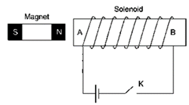
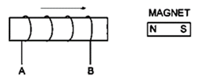
Question 12. The adjacent diagram shows a small magnet placed near a solenoid AB. Current is switched on in the solenoid by pressing the key K. (a) State the polarity at the ends A and B. (b) will the magnet be attracted or repelled? Give a reason for your answer.
Solution:
(a) A – North pole, B – South Pole.
(b) Because current flows counterclockwise at this face and similar poles repel one another, the end of the solenoid closest to the magnet’s North Pole will act as the magnet’s North Pole.
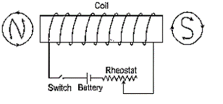
Question 13. The following diagram shows a spiral coil wound on a hollow cardboard tube AB. A magnetic compass is placed close to it. Current it switched on by closing the key. (a) What will be the polarity at the ends A and B? (b) How will the compass needle be affected? Give reason.

Solution:
(a) A – North Pole
B – South Pole
(b) The compass needle’s North Pole will veer westward. The coil’s end A behaves like the North Pole, pushing the compass needle’s North Pole in the direction of the west.
Question 14. State two ways by which the magnetic field due to a solenoid can be made stronger
Solution:
The magnetic field due to a solenoid can be made stronger by using:
(i) By increasing the solenoid’s winding’s number of turns.
(ii) By increasing the solenoid’s current flow.
Question 15. Why does a current carrying freely suspended solenoid rest along a particular direction?
Solution:
When at rest, a solenoid carrying electricity that is hanging freely acts like a bar magnet. The reason for this is that a current-carrying solenoid acts like a bar magnet.
Question 16. What effect will there be on magnetic compass when it is brought near a current carrying solenoid?
Solution:
At that time, the compass needle will be resting in the solenoid’s magnetic field’s direction.
Question 17. How is the magnetic field due to a solenoid carrying current affected if a soft iron bar is introduced inside the solenoid?
Solution:
If a soft iron bar is put within a solenoid that is conducting electricity, the magnetic field generated by the solenoid rises.
Question 18. Complete the following sentence:
(i) When current flows in a wire, it creates ___________.
(ii) On reserving the direction of current in a wire, the magnetic field produced by it gets ___________.
(iii) A current carrying solenoid behaves like a ___________
(iv) A current carrying solenoid when freely suspended, it always rests in ___________ Direction
Solution:
(i) When current flows in a wire, it creates magnetic field.
(ii) On reserving the direction of current in a wire, the magnetic field produced by it gets reversed.
(iii) A current carrying solenoid behaves like a bar magnet .
(iv) A current carrying solenoid when freely suspended, it always rest in north-south direction.
Question 19. You are required to make an electromagnet from a soft iron bar by using a cell, an insulated coil of copper wire and a switch. (a) Draw a circuit diagram to represent the process. (b) Label the poles of the electromagnet.
Solution:
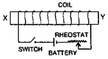
Question 20. The adjacent diagram shows a coil would around a soft iron bar XY. (a) State the polarity at the end X and Y as the switch is pressed. (b) Suggest one way increasing the strength of electromagnet so formed.
Solution:
(a) X-north pole
Y –South Pole.
(b) By using a rheostat to boost current while decreasing circuit resistance
Question 21. (a) What name is given to a cylindrical coil of a diameter less than its length?
(b) If a piece of soft iron is placed inside the coil mentioned in part (a) and current is passed in the coil from a battery, what name is then given to the device so obtained?
(c) Give one use of the device mentioned in part (b).
Solution:
(a) Solenoid is a cylindrical coil with a diameter that is less than its length.
(b) An electromagnet is the resultant device.
(c) An electric relay uses it.
Question 22. Show with the aid of a diagram how a wire is wound on a U-shaped piece of soft iron in order to make it an electromagnet. Complete the circuit diagram and label the poles of the electromagnet.
Solution:

Simply put, an electromagnet is a coil of wire. Normally, it is coiled around an iron core. It may, however, be twisted around an air core, in which case it would be referred to as a solenoid. The electromagnet energizes when it is attached to a current source, producing a magnetic field that is similar to that of a permanent magnet. The amount of current flowing through the electromagnet’s wire directly relates to the magnetic flux density.
The direction of the current determines the polarity of the electromagnet. We use our right hand to locate the electromagnet’s North Pole. If we round the coil with our fingertips in the same direction as the current is moving (typical current moves from + to -). The magnetic field travels in the direction that our thumb is pointing, thus north would emerge from the electromagnet in that same direction. An electromagnet with a horseshoe-shaped core is shown in the circuit diagram above, with the poles noted and the current’s direction specified.
Question 23. (i) What is an electromagnet?
(ii) Name two factors on which the strength of magnetic field of an electromagnet depends and state how does it depend on the factors stated by you.
Solution:
(i) When electricity travels through the coil that is twisted around it, an electromagnet transforms a piece of soft iron into a momentary powerful magnet. It is a made-up magnet.
(ii) An electromagnet’s magnetic field strength is influenced by:
a) Turns: As the solenoid’s winding turn’s increase, the intensity of the magnetic field also does.
b) Current: As the current flowing through the solenoid is increased, the magnetic field’s intensity increases.
Question 24. In the following Figure shows the current flowing in the coil of wire wound around the soft iron horseshoe core.
(i) State the polarities developed at the ends A and B.
(ii) How will the polarity at the ends A and B change on reversing the direction of current?
(iii) Suggest one-way increase the strength of magnetic field produce.

Solution:
(i) At A-south pole and at B-north pole.
(ii) Also, polarity will change. The North Pole will be A, while the South Pole will be B.
(iii) by expanding the turn count.
Question 25. State two ways through which the strength of an electromagnet can be increased
Solution:
The strength of an electromagnet can be increased by following ways:
(i) By increasing the solenoid’s winding’s number of turns.
(ii) By increasing the solenoid’s current flow.
Question 26. Name one device that uses an electromagnet.
Solution:
Device that uses an electromagnet is: Electric bell
Question 27. State two advantages of an electromagnet over a permanent magnet
Solution:
1. A powerful magnetic field can be created using an electromagnet.
2. By adjusting the current flowing through an electromagnet’s solenoid, the intensity of the magnetic field may be quickly altered.
Question 28. State two differences between an electromagnet and a permanent magnet
Solution:

Question 29. Why is soft iron used as the core of the electromagnet in an electric bell?
Solution:
Only while an electric current passes through the solenoid does the soft iron bar develop magnetic qualities; when the current is cut off, the magnetic properties are lost. Because of this, the electromagnet’s core of an electric bell is made of soft iron.
Question 30. How is the working of an electric bell affected, if alternating current be used instead of direct current?
Solution:
The electromagnet’s core will become magnetic if an a.c. source is used instead of a battery, but the polarity at its ends will shift. Pressing the switch will still cause the bell to ring since the polarity of the electromagnet has no effect on the armature’s attraction.
Question 31. The incomplete diagram of an electric bell is given in Fig 10.21 Complete the diagram and labels its different parts.

Solution:

Question 32. Name the material used for making the armature of an electric bell. Give a reason for your answer.
Solution:
The armature of an electric bell is made of soft iron, which may quickly produce magnetism.
Exercise-10A
Multiple Choice Types
Question 1. The present of magnetic field at a point can be detected by :
a) A strong magnet
b) A solenoid
c) A compass needle
d) A current carrying wire
Solution: c) The presence of magnetic field at a point can be detected by a compass needle.
Question 2. By reversing the direction of current in a wire, the magnetic field produced by it:
a) Gets reversed in direction
b) Increases in strength
c) Decreases in strength
d) Remains unchanged in strength and direction
Solution: a) By reversing the direction of current in a wire, the magnetic field produced by it gets reversed in direction.
Exercise-10B
Question 1. Name three factors on which the magnitude of force on a current carrying conductor placed in a magnetic field depends and state how does the force depend on the factors stated by you.
Solution:
When a current-carrying conductor is put in a magnetic field, the strength of the force on it depends on:
(i) The magnetic field strength B
(ii) With conductor current I.
(iii) The conductor’s length.
These three variables all directly affect how much force is exerted on a conductor carrying current when it is exposed to a magnetic field.
Question 2. State condition when magnitude of force on a current carrying
(i) Conductor placed in a magnetic field is Zero?
(ii) Conductor placed in a magnetic field is maximum?
Solution:
(i) The force will be zero when the conductor’s current is flowing in the direction of the magnetic field.
(ii) When the conductor’s current is parallel to the magnetic fie
Question 3. How will the direction of force be changed, if the current is reversed in the conductor placed in a magnetic field?
Solution:
The force’s direction is also reversed.
Question 4. Name and state the law which is used to determine the direction of force on a current carrying conductor placed in a magnetic field.
Solution:
Fleming’s left hand rule: Fleming’s left hand rule states that your thumb, middle finger, and forefinger should all be stretched perpendicular to one another. The thumb will indicate the direction of motion of the conductor if the forefinger shows the direction of the magnetic field and the middle finger indicates the direction of the current.
Question 5. State Fleming’s left handle rule.
Solution:
Fleming’s left hand rule: Fleming’s left hand rule states that your thumb, middle finger, and forefinger should all be stretched perpendicular to one another. The thumb will indicate the direction of motion of the conductor if the forefinger shows the direction of the magnetic field and the middle finger indicates the direction of the current.

Question 6. State the unit of magnetic field in terms of the force experienced by a current carrying conductor placed in a magnetic field
Solution:
Newton/ampere x meter (or NA-1m-1)
Question 7. A flat coil ABCD is freely suspended between the pole pieces of U-Shaped permanent magnet with the plane of coil parallel to the magnetic field.
(i) What happens when a current is passed in the coil?
(ii) When will coil come to rest?
(iii) When will the couple acting on the coil be (i) maximum, (ii) minimum?
(iv) Name an instrument which makes use of the principle stated above.
Solution:
(i) The coil will spin as a result of the torque it experiences.
(ii) When their planes align with the magnetic field normally, the coil will come to rest
(iii) When oil’s plane is parallel to the magnetic field, and when a coil’s plane is perpendicular to the magnetic field.
(iv) The D.C. motor is the device that applies the aforementioned concept.
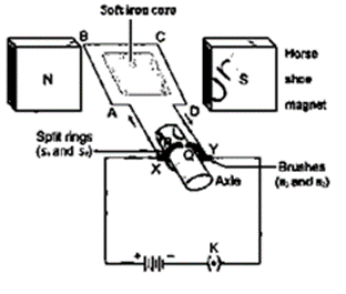
Question 8. A coil ABCD mounted on an axle is placed between the poles N and S of a permanent magnet as shown in Fig. 10.28

(a) In which direction will the coil begin to rotate when current is passed through the coil in the direction ABCD by connecting a battery at the ends A and D of the coil?
(b) Why is a commutator necessary for continuous rotation of the coil?
(c) Complete the diagram with the commutator, etc. For the flow of current in the coil
Solution:
(a) The coil starts to revolve counterclockwise.
(b) This is due to the fact that the arms AB and CD are switched after half of the rotation, which causes the direction of torque on the coil to reverse. After each half-rotation of the coil, a commutator is required to switch the coil’s current direction in order to keep the coil revolving in the same direction.

Question 9. (i) What is an electric motor?
(ii) Principle of an electric motor?
Solution:
(i) An electric motor is a machine that transforms electrical energy into mechanical energy.
(ii) Principle: An electric motor (also known as a dc motor) operates on the idea that when an electric current is carried through a conductor that is generally positioned in a magnetic field, a force occurs on the conductor, causing the conductor to start moving and generating mechanical energy.
Question 10. Draw a labeled diagram of a D.C. motor.
Solution:
Question 11. What energy conversion does take place during the working of a d.c. motor?
Solution:
Mechanical energy may be created from electrical energy.
Question 12. State two ways by which the speed of rotation of an electric motor can be increased
Solution:
The speed of rotation of an electric motor can be increased by:
(i) Increasing the current’s strength.
(ii) Increasing the coil’s number of turns.
Question 13. Name two appliances in which an electric motor is used.
Solution:
Electrical devices including fans, washing machines, juicers, mixers, and grinders among others require electric motors.
Exercise -10B
Multiple Choice Types
Question 1. In an electric motor the energy transformation is :
a) From electrical to chemical
b) From chemical to light
c) From mechanical to electrical
d) From electrical to mechanical
Solution: d) In an electric motor, the energy transformation is from electrical to mechanical.
Exercise-10C
Question 1. (i) What is electromagnetic induction?
(ii) Describe one experiment to demonstrate the phenomenon of electromagnetic induction.
In the figure:
Solution:
(i) Electromagnetic induction: Whenever a conductor’s associated magnetic field lines change, an electromotive force develops between the ends of the conductor that lasts for the duration of the change.
(ii)

(a) There is no deflection in the galvanometer while the magnet is motionless. The cursor indicated “0.”
(b) The galvanometer exhibits a deflection to the right, indicating that a current flows in the solenoid in the direction depicted in [Fig (b)], when the magnet is pushed toward the solenoid with the North Pole facing it.
(c) The galvanometer’s pointer moves to the zero position as soon as the magnet stops moving. This demonstrates that as long as the magnet is moving, current flows through the solenoid.
(d) The solenoid’s current will once more flow if the magnet is pushed away from it, but this time in the opposite direction as illustrated in [Fig. (b)]. and as a result, the galvanometer’s pointer tilts to the left.
(e) The extent of deflection in the galvanometer rises even if the direction of deflection stays the same when the magnet is pulled away quickly, or with increased velocity. That more current is flowing now is evident.
(f) The pointer of the galvanometer will deflect to the left [Fig. (e)] if the polarity of the magnet is reversed, and the magnet is then moved in the direction of the solenoid with the current flowing in the opposite direction to that indicated in Fig. (b).
Question 2. State Faraday’s law of electromagnetic induction.
Solution:
Faraday’s formulated two laws of electromagnetic induction:
(i) An e.m.f. is induced whenever the magnetic flux connected to a coil changes. As long as there is a change in the magnetic flux associated with the coil, the induced e.m.f. will continue to exist.
(ii) The magnetic flux associated to the coil changes at a rate precisely proportionate to the amount of the induced e.m.f. A stable e.m.f. is induced if the rate of change of magnetic flux stays uniform.
Question 3. State two factors on which the magnitude of induced e.m.f. depend.
Solution:
Magnitude of induced e.m.f depends upon:
(i) The fluctuation in magnetic flux
(ii) The moment at which there is a shift in the magnetic flow.
Question 4. (i) What kind of energy change takes place when a magnet is moved towards a coil having a galvanometer at its ends?
(ii) Name the phenomenon?
Solution:
(i) Electrical energy transforms from mechanical energy.
(ii) Electromagnetic induction is a phenomenon.
Question 5. (a) How would you demonstrate that a momentary current can be obtained by the suitable use of a magnet, a coil of wire and a galvanometer?
(b) What is the source of energy associated with the current obtained in part (a?)
Solution:

(a) The magnetic flux associated with the coil varies whenever there is a relative motion between the coil and the magnet. The magnetic flux through the coil rises when the magnet’s North Pole is brought nearer the coil, as seen in the above figure. An e.m.f. is induced in the coil as a result of a change in the magnetic flux connected to it. If the coil’s circuit is closed, this e.m.f. causes a current to flow in the coil.
(b) Mechanical energy serves as the source of energy for the current acquired in section (a).
Question 6. (i) Describe briefly one way producing an induced e.m.f?
(ii) State one factor that determines the magnitude of induced e.m.f?
(iii) What factor determines the direction of induced e.m.f?
Solution:
(i) Induced current can be produced by following activity:

(a) The galvanometer does not deflect while the magnet is stationary. The cursor indicated “0.” (b) The galvanometer deflects to the right when the magnet is pushed toward the solenoid with the North Pole facing the solenoid, indicating that current flows in the solenoid in the direction depicted in Fig (b)
(c) As the magnet’s motion comes to a stop, the galvanometer’s pointer moves to the zero position. This demonstrates that as long as the magnet is moving, current flows through the solenoid.
(d) The solenoid’s current will once more flow if the magnet is pushed away from it, but this time in the opposite direction as illustrated in Figure, and as a result, the galvanometer’s pointer tilts to the left Figure.
(e)The extent of deflection in the galvanometer rises even if the direction of deflection stays the same when the magnet is pulled away quickly, or with increased velocity. That more current is flowing now is evident.
(f)The pointer of the galvanometer will deflect to the left [Fig. (e)] if the polarity of the magnet is reversed, and the magnet is then moved in the direction of the solenoid with the current flowing in the opposite direction to that indicated in Fig. (b).
(ii) Magnitude of the induced e.m.f. depends on:
(a) The alteration in magnetic flux.
(b) The interval during which the magnetic flux changes
(c) Whether there is a rise or decrease in the magnetic flux affects the direction of the induced e.m.f.
Question 7. Complete the following sentence:
The current induced in a closed circuit only if there is ___________.
Solution:
Current induced in a closed circuit only if there is change in number of magnetic field lines linked with the circuit.
Question 8. In which of the following case does the electromagnetic induction occur?
(i) A current is started in a wire held near a loop of wire?
(ii) The current is stopped in a wire held near a loop of wire.
(iii) A magnet is moved through a loop of wire.
(iv) A loop of wire is held near a magnet.
Solution:

Question 9. A conductor is moved in a varying magnetic field. Name the law which determines the direction of current induced in the conductor.
Solution:
The direction of current produced in the conductor is determined by Fleming’s right hand rule.
Question 10. Name and state the law which determines the direction of induced current.
Solution:
Fleming’s right hand rule states that your thumb, middle finger, and forefinger should all be stretched perpendicular to one another. The middle finger represents the direction of induced current if the forefinger indicates the direction of the magnetic field and the thumb the direction of the conductor’s motion.
Question 11. What is Lenz’s law?
Solution:
According to Lenz’s law, induced e.m.f. (or induced current) always tends to go in the opposite direction of the thing that causes it.
Question 12. Why is it more difficult to move a magnet towards a coil which has large number of turns?
Solution:
A coil with more turns will have a larger induced e.m.f., which will cause it to oppose more according to Lenz’s law.
Question 13. Explain why an induced current must flow in such a direction so as to oppose the change producing it.
Solution:
In order for the mechanical energy used to create the change to be converted into electrical energy in the form of an induced current.
Question 14. Explain the significance of Lenz’s law to show the conservation of energy in electromagnetic induction.
Solution:
The law of conservation of energy is implied by Lenz’s law. It demonstrates how the mechanical energy required to exert force against the rotating magnet’s opposing force is converted into the electrical energy required to cause current to flow through the solenoid.
Question 15. The diagram in shows a coil of several turns of copper wire near a magnet NS The coil is moved in the direction of arrow shown in the diagram.
(i) In what direction does the induced current flow in the coil?
(ii) Name the law used to arrive at the conclusion in part (i).
(iii) How would the current in coil is altered if
(a) The coil has twice the number of turns,
(b) The coil was made to move three times fast?
Solution:
(i) The North Pole produces at this end of the coil when it is moved in the direction of the magnet, and current begins to flow from A to B.
(ii) Lenz’s law used to arrive at the conclusion in part (i).
(iii)
(a) Because current directly correlates to the number of turns, it will likewise increase by two
(b) Current multiplies by three.
Question 16. The following diagram shows a fixed coil of several turns connected to a
center zero galvanometer G and a magnet NS which can move.
(a) Describe the observation in the galvanometer if
(i) The magnet is moved rapidly in the direction of arrow,
(ii) The magnet is kept still after it has moved into the coil,
(iii) The magnet then rapidly pulled out the coil.

(b) How would the observation alter if a more powerful magnet is used?
Solution:
(a)
(i) A deflection in the galvanometer occurs when the magnet is moved quickly in the direction of the arrow, changing the magnetic flux associated with the coil and showing a flow of current through the coil.
(ii) When the magnet is held constant, the magnetic flux associated with the coil does not change and the galvanometer does not deflect, proving that the coil is not conducting any current.
(iii) When the magnet is quickly removed, the magnetic flux associated with the coil changes once more, and the galvanometer displays a deflection, but this time in the other direction, showing that a current is flowing in the coil in the opposite direction.
(b) A stronger magnet will cause a larger deflection in the galvanometer, indicating a higher current level.
Question 17. Name and state the principle of a simple a.c. generator what is its use?
Solution:
The “electromagnetic induction” theory underlies how an A.C. generator operates. An EMF is generated between a coil’s ends whenever it is spun in a magnetic field because this affects the magnetic flux associated with the coil. When a load-containing external circuit is linked between the ends of a generator’s coil, the generator then behaves like a source of current.
Question 18. What determines the frequency of a.c. produced in a generator?
Solution:
The number of coil revolutions per second or the coil’s rotational speed
Question 19. Complete the sentence:
An A.C. generator changes the ___________ energy to ___________ energy.
Solution:
Mechanical, Electrical
Q20. Draw a labeled diagram of a simple a.c. generator.
Solution:

Question 21. In an a.c. generator the speed at which the coil rotates is doubled. How would this affect (a) the frequency of output voltage, (b) the maximum output voltage is doubled.
Solution:
(a) In an a.c. generator, double the coil’s rotational speed doubles the frequency.
(b) The highest possible output voltage has likewise doubled.
Question 22. Suggest two ways in an a.c. generator to produce a higher e.m.f.
Solution:
Two ways in an a.c generator to produce a higher e.m.f. are:
(1) By accelerating the coil’s rotational speed.
(2) By extending the coil’s number of turns.
Question 23. What energy conversion does take place in a generator when it is in use?
Solution:
Electrical energy is converted from mechanical energy.
Question 24. (a) State two dis-similarities and one similarity between a D.C. motor and an A.C. generator.
(b) Give two differences between a D.C. motor and an a.c. generator.
Solution:
Two dissimilarities between D.C. motor and A.C. generator:

(b) Similarity: A coil rotates in a magnetic field between the pole pieces of a strong electromagnet in both an A.C. generator and a D.C. motor.
Question 25. State one advantage of using A.C. over D.C.
Solution:
Before transferring electricity across long distances, the voltage of a.c. can be increased at the power generating station using a step-up transformer. It lessens electrical energy loss through heat generation in transmission line cables. A significant amount of electrical energy will be lost as heat in the transmission line wires if, on the other hand, direct current (D.C.) is generated at the power plant and its voltage cannot be adjusted for transmission.
Question 26. For what purpose are the transformers used? Can they be used with a direct current source?
Solution:
The transformer’s function is to increase or decrease the a.c. voltage. No, you cannot use a transformer with direct current.
Question 27. State two factors on which the magnitude of an induced e.m.f. in the secondary coils of a transformer depends.
Solution:
The magnitude of an induced e.m.f. in the secondary coil of a transformer depends on the following two factors.
a) The proportion between the secondary coil’s and primary coil’s turn counts.
b) The amount of applied e.m.f. in the primary coil.
Question 28. How is the e.m.f in the primary and secondary coils of a transformer related with the number of turns in these coils?
Solution:
The relation is following:
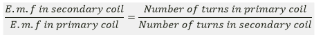
Here,
S:- stands for secondary
P:- Stands for primary
Question 29. Draw a labeled diagram to show the various components of a step-up transformer.
Solution:
Step up transformer:

Question 30. Name the device used to transform 12V A.C. to 200V A.C. Name the principal on which it works.
Solution:
The tool is a transformer step-up. The electromagnetic induction theory underlies its operation.
Question 31. Draw a labeled diagram of a step-up transformer and explain how it works. State two characteristics of the primary coil as compared to its secondary coil
Solution:

Step-up transformer: A low voltage alternating electromagnetic field is converted to a high voltage alternating electromagnetic field of the same frequency using a step-up transformer.
Working: When the main coil’s terminals are linked to the source of alternating e.m.f., a fluctuating current runs through it, producing a fluctuating magnetic field in the transformer’s core as a result. As a result, the magnetic field lines connected to the secondary coil change, causing the secondary coil to produce an e.m.f. The applied e.m.f. in the main coil fluctuates similarly to how the induced e.m.f. does, thus it has the same frequency as the applied e.m.f.
The “turns ratio” and the strength of the applied e.m.f. both affect how much induced e.m.f. is present in the secondary coil.
For a transformer,

= Turns ratio (n)
Two characteristics of the primary coil as compared to its secondary coil:
1. The primary coil’s number of turns is lower than the secondary coil’s number of turns.
2. In comparison to the secondary coil, a thicker wire is employed in the main coil.
Question 32. Draw a labeled diagram of a device you would use to transform 200V A.C. to 15V A.C. Name the device and explain how it works. Give its tow uses.
Solution:
The device is step-down transformer.
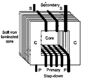
Working: In a step-down transformer, the number of turns in secondary coil are less than the number of turns in the primary coil i.e., turns ratio

Two uses of step down transformer are: In order to step-down the voltage before it is distributed to the customers,
(i) Electric bells
(ii) Are used at the electricity sub-stations.
Question 33. Name the coil of which the wire is thicker in a (i) step up, (ii) step down transformer. Give reason to your answer.
Solution:
(i) In the case of a step-up transformer, the main coil’s wire is thicker than the secondary coil’s.
(ii) The secondary coil of a step-down transformer has thicker wire than the primary coil.
The loss of energy as heat in the coil is decreased by using thicker wire since it has less resistance. In the step-up, NS > NP leads to ES > EP, but is IP, meaning that the primary coil receives higher current flow. The situation with a step-down transformer is the opposite. As a result, the wire’s thickness is selected appropriately.
Question 34. Complete the following diagram of a transformer and name the parts labeled A and B. name the part you have drawn to complete the diagram. What is the material of this part? Is this transformer a step up or step down? Give reason.

Solution:

The main coil is A. The secondary coil is labeled B. In the diagram, we have a laminated core depicted. This component is made of soft iron. The main coil of this transformer has a lot more turns than the secondary coil, making it a step-down transformer.
Question 35. The following diagram shows the core of a transformer and its input and output connections.
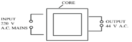
(a) State the material used for core and describe its structure.
(b) Complete the diagram of the transformer and connections by labeling all parts joined by you.
(c) Name the transformer: Step-up or step down?
Solution:
(a) The core is made of soft iron. The thin, T- and U-shaped, soft iron sheets that make up the core are alternatively stacked one on top of the other and separated from one another by a paint or varnish covering.
(b)
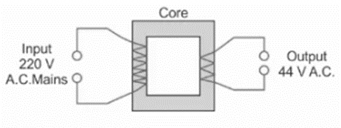
(c) It is a step-down transformer.
Question 36. The secondary windings of a transformer in which the voltage is stepped down are usually made of thicker wire than the primary. Explain why.
Solution:
Because greater current passes through the secondary coil of a transformer where the voltage is stepped down, the secondary windings are often thicker than the primary. The waste of energy as heat in the coil is decreased by using thicker wire, which has lower resistance.
Question 37. Why the iron core of a transformer is made laminated (thin sheets) instead of being in one solid piece?
Solution:
To minimize the eddy currents’ energy losses
Question 38. Complete the following sentence:
(i) In a step-up transformer, the number of turns in the primary are __________ than the number of turns in the secondary.
(ii) The transformer is used in __________ current circuits.
(iii) In a transformer, the frequency of A.C. voltage _________.
Solution:
(i) In a step-up transformer, the number of turns in the primary is less than the number of turns in the secondary.
(ii) The transformer is used in alternating current circuits.
(iii) In a transformer, the frequency of A.C. voltage remain same.
Question 39. What is the function of a transformer in an a.c. circuit? How do the input and output powers in a transformer compare?
Solution:
A transformer is a tool used to change the amplitude of an alternating electromagnetic field.
When there is no energy loss in a perfect transformer, the output power is equal to the input power, or vice versa.
Power in secondary coil = power in primary coil ESLS = EPLS
Question 40. Name two kind of energy loss in a transformer. How is it minimized?
Solution:
The term “copper loss” refers to the energy loss in a transformer.
Losses in copper: Copper wire often makes up a transformer’s primary and secondary coils. There is resistance in these copper cables. A portion of the energy used to move the current via these wires is wasted as heat. Copper loss is the term used to describe the energy lost via the transformer’s windings.
By employing thick wires for the windings, this loss may be reduced to a minimum. Use of thick wire lowers resistance, which lowers the coil’s waste of energy as heat.
Eddy current-related loss utilizing laminated core helps reduce it.
Question 41. Give two points of difference between a step-up transformer and step-down transformer.
Solution:

Question 42. Name the material of core in (a) electric bell, (b) electromagnet (c) d.c motor, (d) an a.c. generator and (e) transformer.
Solution:
Soft iron is used in all.
Question 43. Name the transformer used in the
(i) Power generating station,
(ii) Power sub-station.
State the function of each transformer.
Solution:
(i) Step-up transformer. The alternating current produced in power plants is first raised in voltage from 11 kV to 132 kV.
(ii) Step-down transformer:-
Before being distributed to the customers, voltage is stepped down at the electricity sub-station. Transformers are utilised to lessen energy loss in the form of heat in the transmission line wires.
Exercise-10C
Multiple Choice Types
Question 1. The direction of induced current is obtained by:
a) Fleming’s left hand rule
b) Clock rule
c) Right hand thumb rule
d) Fleming’s right hand rule
Solution: d) Fleming’s right hand rule
Question 2. In a step up transformer:
a) Ns = Np
b) Ns < Np
c) Ns > Np
d) nothing can be said
Solution: c) Ns > Np
Exercise-10C
Numerical
Question 1. The magnetic flux through a coil having 100 turns decreases from 5 milli weber to zero in 5 second. Calculate the e.m.f. induced in the coil.
Solution:
It is given that,
Decrease in the flux = 0.005 – 0 = 0.005 weber
Number of turns = 100 turns and
Time = 5 second
E.m.f. induced e = N × Rate of increase of magnetic flux =100×0.005/5
E.m.f. induced e = 0.1 V = 100Mv
Question 2. The primary coil of a transformed has 800 urns and the secondary coil has 8 turns. It is connected to a 220 V a.c. supply. What will be the output voltage?
Solution:
No. of turns in primary coil Np=800
No. of turns in secondary coil Np=8
Input supply voltage Ep = 220 V
E_p/E_s

Question 3. A transformer is designed to work from a 240 V a.c. mains and to give a supply of 8 V to ring a house–bell. The primary coil has 4800 turns. How many turns will be in the secondary coil?
Solution:
Input ac voltage Ep = 240 V.
Number of turns in primary coil Np = 4800
No. of turns in secondary coil Ns=?
Output voltage Es = 8 V.
We know that

Question 4. The input and output voltage of a transformer are 220 V and 44 V respectively. Find:
(i) The turn’s ratio.
(ii) The current in input circuit if the output current is 2 A.
Solution:
(i) We know that