Students should refer to Magnetism ICSE Class 10 Physics notes provided below designed based on the latest syllabus and examination pattern issued by ICSE. These revision notes are really useful and will help you to learn all the important and difficult topics. These notes will also be very useful if you use them to revise just before your Physics Exams. Refer to more ICSE Class 10 Physics Notes for better preparation.
ICSE Class 10 Physics Magnetism Revision Notes
Students can refer to the quick revision notes prepared for Chapter Magnetism in Class 10 ICSE. These notes will be really helpful for the students giving the Physics exam in ICSE Class 10. Our teachers have prepared these concept notes based on the latest ICSE syllabus and ICSE books issued for the current academic year. Please refer to Chapter wise notes for ICSE Class 10 Physics provided on our website.
Magnetism ICSE Class 10 Physics
Characteristics of a Magnetic Field Produced By Current Carrying Conductors
When a magnetic compass is brought near a current carrying wire, the compass needle gets deflected. Why does this happen?
The compass needle suffers deflection because a current carrying wire produces magnetic field lines around it.
Construct a simple open circuit with two open ends M and N respectively. Take a piece of aluminium wire and connect it with the two open ends. Now, bring a magnetic compass close to the aluminium wire and wait till the compass needle comes to rest. Now, allow the current to flow through the wire and notice the direction of deflection of the North pole of the compass needle with respect to the direction of the current flowing through the wire.
Now, switch off the current and reverse the direction of the current by reversing the polarities of the battery. Now, switch on the current and observe the deflection of the North pole of the compass needle. You will find that the compass needle in this case gets deflected in the opposite direction. Why does this happen?

This happens because the direction of the magnetic field lines produced around a conductor depends on the direction of the current flowing through it. Hence, the direction of the magnetic field lines gets reversed when the direction of the current flowing through the conductor is reversed.
Pattern of magnetic field lines around a current carrying a straight conductor
Similar to bar magnets, a current carrying a straight conductor also has magnetic field lines around it. What factors are responsible for the pattern of magnetic field lines?
To understand the pattern of magnetic field lines around a current carrying a straight conductor, we will perform the following activity:
Using a rheostat box, a 12 V battery, and a key, construct a simple open electric circuit with open ends M and N respectively (you can obtain a rheostat box from your science laboratory). Now, take a cardboard sheet and insert an aluminium wire through the centre of the sheet.
Connect the open ends of the wire with the open ends M and N of the circuit. Now, spread a few but equal iron filings over the sheet in such a way that the sheet stays horizontal. Now, turn the knob of the rheostat box to maximum to allow the current to pass through the circuit and the aluminium wire.

Now, turn the knob of the rheostat box slowly to lower the resistance and observe the movement of the iron filings. You will see that the iron filings arrange themselves in a regular pattern. Can you identify that regular pattern?
You will find that the iron filings align themselves in concentric circles around the conductor. What does this represent?
This represents that concentric magnetic fields are produced in the form of concentric circles around a current carrying the conductor.
How is the direction of concentric magnetic fields around the conductor related with the direction of current?
To understand this, slowly bring a magnetic compass near the aluminium wire and observe its deflection. Now, turn the knob of the rheostat slowly from its maximum value to its minimum value and simultaneously observe the direction of deflection of the North Pole of the compass needle. The compass needle deflects clockwise with an increased magnitude.
Now, switch off the current and reverse the polarities of the battery so that the direction of the current gets reversed. Keep the rheostat at its maximum value. Turn the key on and increase the current by turning the knob of the rheostat box towards its minimum value.
You will find that as current increases, the deflection of the needle in an anti-clockwise direction also increases. Now, reduce the current slowly. What change in deflection of the needle do you observe?
You can see that the deflection in the needle also decreases. Therefore, we can say that the strength of a magnetic field produced around a straight current carrying conductor is directly proportional to the magnitude of the current.
Similarly, if you move the compass away from the current carrying a wire, then you will notice that the deflection in the compass needle decreases and vice-versa.
Hence, from the above discussion, we find that the magnitude of the magnetic field produced by a straight current carrying a wire at a given point is
(i) directly proportional to the strength of the current passing through the wire
(ii) inversely proportional to the distance of this point from the wire
The direction of magnetic fields around a conductor is given by the right hand thumb rule.
Right hand thumb rule
Magnetic field due to a current carrying a circular loop
When a straight wire is bent, it becomes a circular loop. What happens when a current is allowed to pass through a circular loop? Will the circular magnetic fields produced around the current carrying a straight conductor also bend when the conductor is bent?
To understand the pattern of magnetic field lines around a current carrying a straight conductor, we will perform the following activity:

Take a rectangular cardboard sheet with two holes M and N respectively. Insert the two ends of a circular loop of the wire into the holes respectively. Now, connect both ends with a circuit (as shown in the following figure). Before closing the key, spread some iron filings over the sheet.
Hold the board gently and observe the pattern formed by the iron filings on it. You will find a regular pattern. Can you explain the origin of this regular pattern?
When a current is passed through a circular loop of wire, magnetic field lines are produced that pass through the loop in the direction normal to the loop area (given by Maxwell’s right hand rule).
Every point on the current carrying wire produces its own concentric field lines with its centre at the point. The produced magnetic field lines are circular near the current carrying the loop. As we move away from the wire, concentric circles representing magnetic field lines become bigger, indicating that the strength of the produced
magnetic force decreases gradually.
The magnitude of the field lines produced by a circular loop at its centre is
1. directly proportional to the amount of current
2. inversely proportional to the radius of the loop
Magnetic field due to a current carrying a solenoid
A solenoid is a long straight insulated wire, often wrapped around a cylinder-shaped body. A copper coil is wound around a cylindrical core, such that the core’s diameter is lesser than its length. It produces a magnetic field when electric current is passed through it. A strong magnetic field is produced inside a solenoid when a current is allowed to pass through it.

The given diagram shows the produced magnetic field lines when a current flows through a solenoid. The field lines are parallel inside (indicating that the magnetic field is uniform inside the solenoid) and curved outside the solenoid. This is similar to the magnetic field lines produced by a bar magnet.
The direction of the magnetic field produced by the solenoid depends on the direction of the current flowing through it. Depending on the direction of the flow of current, one end of the solenoid acts like the North Pole of a magnet while the other end acts like the South Pole. In the figure given above, magnetic lines of force get emanated from the left end and terminate at the right end of the current carrying the solenoid. Hence, the right end of the solenoid acts as the North Pole while the left end acts as the South Pole.
Each turn of the coil behaves like a magnet when electric current is made to flow through it. In the above figure, the current is flowing in a clockwise direction; thus, the left hand side of each coil becomes the south pole, and conversely, the right hand side of each pole becomes the north pole. If we consider small coils as small bar magnets, with their opposite poles kept one after the other, then the entire coil behaves like a bar magnet.
If we take this analogy further (of taking one coil as one small bar magnet), then the more the number of small bar magnets combining to form a large bar magnet, the stronger will be the magnetic field of the complete bar. Hence, we can conclude that the more the number of coils in a solenoid, the stronger is the magnetic field produced by it.
When a solenoid is wound on soft iron, the magnetic field is very strong; but we cannot retain the magnetic property after the current is stopped. In such a situation, a solenoid is called an electromagnet. However, if we use a bar of steel instead soft iron, we can retain its magnetic properties even after the current is stopped. In other words, the bar
of steel becomes a permanent magnet, but its magnetic strength is lesser than that of soft iron.
The strength of the magnetic field produced by a current carrying a solenoid
(i) is directly proportional to the number of turns in the solenoid
(ii) is directly proportional to the strength of the current in the solenoid
(iii) depends upon the nature of the core material
For example, the use of core materials such as soft iron increases the magnetic field.
Soft iron core is placed inside the transformer core to increase the magnetic field.

Construct a simple circuit using a solenoid. Place a magnetic compass near the solenoid and close the switch. The compass needle will deflect in a direction. Now, move the compass slowly near one end of the solenoid and observe the position of the needle. You will observe that the needle gets aligned horizontally along the length of the solenoid.
Try to explain this with the help of Maxwell’s right hand rule. Now, bring the compass near the other end. You will find that the compass needle gets aligned horizontally in the opposite direction. Can you explain why the needle reverses its direction when moved from one end to the other of the current carrying the solenoid?
Games C. Maxwell (1831 – 1879) was one of the great physicists and mathematicians of the 19th century. He gave a unified model for electricity and magnetism called electromagnetism with his four sets of electromagnetic equations. He predicted the direction of the magnetic field produced around a current carrying a wire.
Permanent Magnets and Electromagnets
Amar watches his father fix an electric bell in their new house. He wonders how a bell produces such a loud sound when its switch is pressed on.
In this section, we will learn about the construction and working of an electric bell.
An electric bell works on the principle of electromagnetism.
Let us show you the working of an electric bell.
Hans Christian Oersted (1777-1851) was one of the greatest physicists of his time. Until 1820, it was believed that only natural magnets were able to possess magnetism. In 1820, Oersted suggested that a wire behaves similar to a magnet when an electric current passes through it. He was the first scientist to demonstrate the magnetic effect of current.
Now, if you switch off the current in the previous experiment, then what would you expect to observe? Would the needle return to its previous position? If yes, then why?

You will observe that the needle returns to its original position. This happens because the wire carries no current when the switch is off. Hence, the phenomenon of the magnetic effect of current does not apply here.
Reverse the terminals of the cell by reversing the cell and bring the compass near the circuit again, as shown in the given figure.

Switch on the current in the circuit and observe the deflection in the compass needle. Does the needle deflect in the same direction as in the previous case?
You will observe that the needle is deflected in a direction opposite to that in the earlier case. This happens because the direction of current in the wire is opposite to that in the earlier case.
The direction of deflection of a compass needle depends on the direction of the current flowing in the wire.
The phenomenon of the magnetic effect of current is used in various fields in our day-today life. One such use of the magnetic effect of current is illustrated below.
Puneet visited a junkyard on a school education trip. In the junkyard, he saw the arm of a crane, with a large magnet at its bottom, move over a heap of junk and collect objects made of iron. The magnet used in a junkyard crane is not a natural or a permanent magnet. It is a temporary magnet, which is called an electromagnet. As its name suggests, its magnetic nature depends on the presence of an electric current.
Construction of an electromagnet
Take a long piece of insulated copper wire and an iron nail. The wire must be insulated i.e., it must be covered by plastic in order to prevent short-circuiting, which is caused by the contact of wires. Make a coil from this wire by winding it around the iron nail. Now, construct an electric circuit that consists of a cell, a switch, and the two ends of the coil, as shown in the given circuit diagram.

After constructing the electric circuit, switch on the current in the coil by closing the switch and bring a paper clip near one end of the nail. What do you observe? Does the paper clip get attracted towards the end of the nail and get attached to it?
When the switch is ON, the nail in the circuit behaves like a magnet. When a magnetic material such as an iron nail is placed within a current-carrying coil, it behaves like a magnet called electromagnet.
Types of an electromagnet
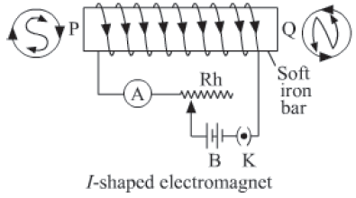
• Bar-shaped or I-shaped electromagnet: To create such an electromagnet, a thin insulated copper wire is wound in a form of a solenoid on a soft iron bar. When current passes through this wire, the bar starts behaving like an electromagnet.
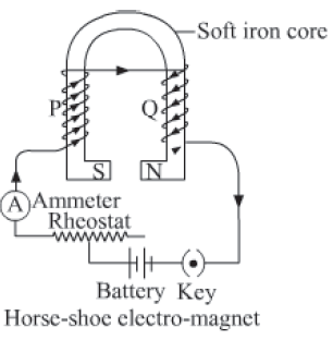
• Horse-shoe or U-shaped electromagnet: This electromagnet is constructed when a thin insulated copper wire is spirally wound on the arms of the horse-shoe shaped soft iron core. The wire is wound in such a way that when the winding is seen from both the ends, they appear to be in opposite sense on the two arms.
What will happen to the paper clip when you open the switch? Will it remain attached to the nail?
• A magnetic material will act as an electromagnet till the time current continues to pass through it.
• When the current stops flowing, the material loses all its magnetic properties andbehaves like a normal material.
The principle of electromagnetism is used in various devices such as electric bell, electric fan, etc.
The strength of an electromagnet depends on the
• total number of turns in the coil of wire
• strength of the current in the coil
• characteristics of the magnetic material over which the wire is wound
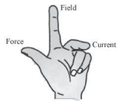
Fleming’s Left Hand Rule
It is clear from the above activity that a current carrying the rod experiences a force when placed between two poles of strong magnets. The direction of displacement of the rod reverses when the direction of current is reversed. This suggests that the direction of force exerted on the rod is related with the direction of current.
Repeat the same process by reversing the direction of the magnetic field. You can easily observe that the rod will displace towards the right when the current flows from Q to P, and displaces towards the left when the current flows from P to Q. What does this suggest?
This suggests that the direction of force exerted on the rod is related with the direction of the magnetic field. Thus, we can say that the directions of current, magnetic field, and magnetic force are perpendicular to each other.
Experimentally, it is found that the magnitude of this force depends upon three factors:
(1) F I (current I flowing in the rod)
(2) F I (strength of magnetic, field B)
(3) F I (lenght of the rod I)
Combining equations (1), (2) and (3) we get F ∝ IBl = KIBl
where K is a constant and its value in SI unit is 1. So, F = IBl
Apply Fleming’s left hand rule to find the direction of this magnetic force.
Fleming’s left hand rule
This rule states that if you stretch the thumb, index finger, and middle finger of your left hand such that they are mutually perpendicular to each other, then your index finger represents the direction of the field, the middle finger represents the direction of the current, and the thumb represents the direction of the force experienced by the
conductor.
A charged particle is moving between two poles of magnets (as shown). Using Fleming’s left hand rule, find out the direction of the magnetic force exerted on the particle?

Do You Know:
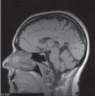
Magnetic field is always produced by an electric current. The ions dissolved in blood move along the nerve cells. Thus, they produce a magnetic field, although a weak one. They produce sensations that we sense through the skin. This is because when we touch, the nerve cells transport an electric impulse to the specific part of our body that we have to use. A short lived magnetic field is produced there, which allows us to sense. Magnetic resonance imaging (MRI) is primarily a technique that uses magnetism, which is produced in our nerve cells to obtain computerised images of internal parts of our body such as the heart, brain etc.
Electric Motor
An electric motor is a rotating device that converts electrical energy into mechanical energy. A number of household devices such as fans, mixers, grinders, washing machines etc. consist of a motor.
Do you know how an electric motor works?
Motor principle
The basic principle on which the electric motor works is the magnetic effect of current. A current carrying a rectangular coil starts rotating when placed in a magnetic field. This happens because a continuous magnetic force acts upon it. Rotation of the coil also results in the rotation of the shaft attached to it. Thus, through this process, a motor converts electrical energy into mechanical energy. Construction of an electric motor
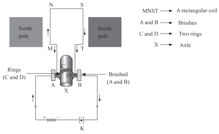
The given figure illustrates the internal parts of a simple electric motor. A motor consists of a rectangular coil MNST of insulated copper wire. The coil is placed between two magnetic poles such that the magnetic field acts normal on lengths MN and ST.
The coil is connected with two carbon brushes at points A and B respectively. The inner sides of these carbon brushes are in contact with half rings C and D, which are insulated and in contact with an axle (not shown in the figure).
Functioning of an electric motor
When a current is allowed to flow through the coil MNST by closing the switch, the coil starts rotating anti-clockwise. Why does this happen? This happens because a downward force acts on length MN and at the same time, an upward force acts on length ST. As a result, the coil rotates anti-clockwise.

The current in length MN flows from M to N, and magnetic field acts from left to right normal to length MN. Hence, according to Fleming’s left hand rule, a downward force acts on length MN. Similarly, the current in length ST flows from S to T, and magnetic field acts from left to right normal to its length. Hence, an upward force acts on length
ST. These two forces cause the coil MNST and the axle to rotate anti-clockwise.
After half-rotation, the position of length MN and ST get interchanged. Simultaneously, half ring D comes in contact with brush A and half ring C comes in contact with brush B respectively. Hence, the direction of current in coil MNST gets reversed and flows through TSNM.
An electric device that reverses the direction of current in a circuit is called a commutator.
Thus, the split ring acts as a commutator of the electric motor. Now, due to the reverse direction of current in lengths MN and ST, an upward force acts on length MN, which pushes it up and a downward force acts on length ST, which pushes it down. As a result, the coil MNST further rotates anti-clockwise. The reversal of the current through the coil MNST repeats at each half-rotation, while its anti-clockwise rotation continues.
A commercial motor uses
1. an electromagnet and permanent magnetic poles
2. large number of turns in the rectangular coil
3. A core of soft material such as iron on which the coil is wounded. The core becomes an electromagnet when a current flows through the coil. The coil–core system is known as the armature of motor.
Electromagnetic Induction
Let us perform an activity first.
What would you expect if the same experiment is repeated with the South Pole of the magnet? Will the direction of deflection of the pointer be reversed?
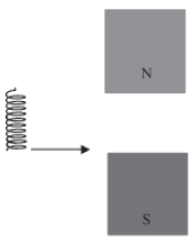
From the above activity, we can conclude that the motion of the magnet sets up a current in the coil, whose direction depends on the nature of the incoming pole as well as on the direction of the motion of the magnet. What happens when the magnet is kept stationary and the solenoid is moved across it?
It is observed that a current is induced in the solenoid when it is moved across a stationary magnet. What does this indicate?
This indicates that a potential difference and current are induced in the solenoid, when either the solenoid or the magnet or both are moving.
The phenomenon of the generation of induced current in a conductor by changing the magnetic field or by moving a conductor in the magnetic field is known as electromagnetic induction.
The voltage generated in the circuit during electromagnetic induction is called electromotive force (e.m.f). Factors influencing induced e.m.f. are:
i) Number of turns of the coil,
ii) Rate of change of magnetic field linked with the coil.
This phenomena was first observed by Faraday. From his observations he enunciated two laws of electromagnetic induction.
First Law: A changing magnetic flux linking with a coil induces an electromotive force in the coil.
Second Law: The induced electromotive force is proportional to the rate of change of magnetic flux linked with the coil.

The direction of induced e.m.f is given by Lenz’s law according to which the direction of induced e.m.f. (or induced current) is such that it opposes the cause which produces it.
Michael Faraday (1791 – 1867) was one of the greatest physicists of the 19th century. Initially, he worked as a book binder in a book shop. He was so interested in experiments of science that he used to read the books that came for binding. He was the first to show that current is induced in a coil when a solenoid, magnet, or both are moved relative to each other. He also discovered the law of electrolysis.

Take a long non-conducting cylindrical rod. Insert two coils of wires M and N on this rod. Ensure that the number of turns in coil M is greater than the turns in coil N. Now, connect a battery and a key to the ends of coil M and connect a galvanometer to the ends of coil N (as shown in the given figure). Allow the current to pass through coil M by closing the switch and observe the pointer of the galvanometer. You will see that the pointer comes back to zero after deflecting by a small amount. What does this indicate?

Deflection of the pointer of the galvanometer indicates that a temporary current is set up in coil N. Now, open the switch to stop the current in coil M. You will see that the pointer again deflects, but in the opposite direction and comes back to zero. This indicates that a current has set up in coil N in the opposite direction.
From the above activity, we observed that as soon as the current in coil M reaches from zero to maximum or from maximum to zero, a current gets induced in coil N. Here, coil M is called the primary coil, while coil N is called the secondary coil.
As a current is always associated with a magnetic field, the change in current in coil M causes a change in the associated magnetic field. This in turn changes the magnetic field around coil N. The change in the magnetic field around coil N generates an induced electric current in the coil. This phenomenon is known as mutual induction.
The working of a transformer is based on the phenomenon of mutual induction.
The direction of the current induced with respect to the directions of the magnetic field and motion of the coil is given by Fleming’s right hand rule.
Fleming’s right hand rule
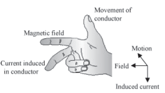
The direction of current induced in a conductor can be obtained by holding the thumb, the index finger, and the middle finger of your right hand mutually perpendicular to each other. In this situation, the thumb indicates the direction of the motion of the conductor, the index finger points along the magnetic field, and the middle finger points along the current induced in the conductor.
A solenoid is moved from left to right in a magnetic field. What will be the direction of current induced in the solenoid?
The phenomenon of electromagnetic induction is used in electric generators for the generation of electricity.
When current in a circuit flows only in one particular direction and does not change its magnitude, it is called Direct current or DC.
When current periodically changes its direction and magnitude about a mean value (called r.m.s. value), it is called Alternating current or AC.
Difference between A.C. and D.C.

Advantage of alternating current over direct current
If a direct current is generated at the power station, its voltage cannot be increased for transmission, and so due to passage of high current in the transmission lines, there will be a huge loss of electrical energy in the form of heat in transmission lines. However, we can increase or decrease the voltage of alternating current for transmission and thus
it reduces heat loss in the transmission line.
Do you know that the current we receive in our houses is AC? Even the current produced in emergency generators and in hydroelectric power houses is alternating current. The alternating current that we use in our homes has a frequency of 50 Hz. It means that the current changes its direction 50 times in a second. The supply of AC voltage is controlled by a transformer.
Electric Generator
An electric generator is a machine that generates electricity by rotating its rotor in a magnetic field. Thus, it converts mechanical energy into electrical energy.
Principle
The basic principle on which electric generator works is electromagnetic induction. When rotor rotates in a magnetic field, current is induced in the rotor.
Construction
A generator consists of a rectangular coil MNST of insulated copper wire placed between two strong magnetic poles. The two ends of the coil MNST are connected with brushes A and B of rings C and D respectively. The inner sides of the rings are insulated. They are attached with an axle X, which can be rotated mechanically. Brushes A and B are connected with a galvanometer that can measure the flow of current in coil MNST.

Working
When the axle is rotated, lengths MN and ST move up and down respectively. Since lengths MN and ST are moving in a magnetic field, a current gets induced in these lengths caused by an electromagnetic induction. The direction of the induced current in both the lengths is given by Fleming’s right hand rule.

Since length MN is moving upwards in the magnetic field that acts from left to right, the direction of the induced current will be from M to N. Similarly, the direction of the induced current in length ST will be from S to T. Hence, an induced current will set up in the coil in the direction MNST, which produces deflection in the galvanometer.
After half-rotation, length MN starts moving down, whereas length ST starts moving up. The direction of the induced current in the coil gets reversed i.e., the induced current will now flow from T to M via S and N i.e., TSNM. Therefore, we can conclude that after each half-rotation, the direction of the induced current is reversed. This current is called an alternating current (AC). An AC reverses its direction after equal time intervals. A machine with this arrangement is called an AC generator.

To get a current that flows in one direction only, a split ring is used.
In this arrangement, brush A always remains in contact with the length moving up, whereas brush B always remains in contact with the length moving down. Here, split rings C and D act as a commutator.
In this case, the direction of the current induced in the coil will be from M to T via N and S for the first half-rotation, and from T to M via S and N for the second half-rotation of coil MNST. Hence, we get a unidirectional current called direct current (DC). A machine with such an arrangement is called a DC generator.
Do You Know:
Electricity supplied to our homes, school buildings, company buildings etc. is AC, which reverses its direction after every second with a frequency of 50 Hz. Most power stations in the world generate AC than DC. This is because AC can be transmitted over very long distances without much loss of energy.
Transformers
Principle − It works on the principle of electromagnetic induction. When current in one circuit changes, an induced current is set up in the neighbouring circuit.

There are two types of transformers.
Step-up transformer:
Step-up transformers are used to increase the ac voltage. In this, the number of turns in the secondary coil is greater than that in the primary coil as shown in the figure.
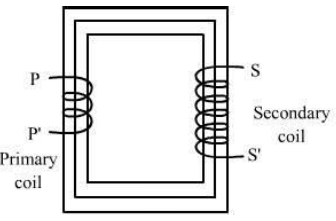
Step-down transformer:
Step-down transformers are used to decrease the ac voltage. In this, the number of turns in secondary coils is less than that in the primary coil as shown in the figure.

Working
An alternating emf is supplied to the primary coil PP’. The resulting voltage is produced as an induced voltage in the secondary coil SS’. Voltage at the primary and the secondary coils depend on the number of turns. Magnetic flux that is linked with the primary coil is also linked with the secondary coil. The induced emf in each turn of the secondary coil is equal to that of the primary coil.
Let,
VP = Alternating emf applied to primary coil
VS = Alternating emf induced to secondary coil
NP − Number of turns in the primary coil
NS − Number of turns in the secondary coil
From the working of a transformer, we observe that the voltage across the coil is directly proportional to the number of turns in the coil.
It means that VP α NP.
So, VP = KP NP (i)
Here, KP is the constant of proportionality.
VS α NS
So, VS = KS NS (ii)
Here, KS is the constant of proportionality.
Dividing equation (ii) by (i)

• For step-up transformer K > 1.
∴ Vs > Vp
• For step-down transformer K < 1.
∴ Vs < Vp
Also, power transfer through the transformer is suppose to be constant.
Input electrical power = Output electrical power
VpIp = VsIs

Transformers are used in telegraph, telephone, power stations, etc.
Losses in a transformer:
Copper loss − Heat in copper wire is generated by working of a transformer. It can be diminished using thick copper wires.
Iron loss − Loss is in the bulk of iron core due to the induced eddy currents. It is minimised by using a thin laminated core.
Hysteresis loss – Alternately, magnetising and demagnetising the iron core cause loss of energy. It is minimised using a special alloy of iron core with silicon.
Magnetic loss − It is due to the leakage of magnetic flux.
Induction Coil:
Induction coil is a device used to convert low DC Voltage to high AC Voltage. It is similar to a transformer and works on the same principle. It usually consists of two coils, the primary coil and the secondary coil. Primary coil consists of few turns of a thick insulated copper wire wound over a soft iron core which is connected to the battery.
The secondary coil has large number of turns which are wound over the primary coil. An interrupter is used for making and breaking the current in the primary coil automatically.
This current magnetizes the iron core and produces a large magnetic field throughout the induction coil.