Students should refer to Electricity ICSE Class 10 Physics notes provided below designed based on the latest syllabus and examination pattern issued by ICSE. These revision notes are really useful and will help you to learn all the important and difficult topics. These notes will also be very useful if you use them to revise just before your Physics Exams. Refer to more ICSE Class 10 Physics Notes for better preparation.
ICSE Class 10 Physics Electricity Revision Notes
Students can refer to the quick revision notes prepared for Chapter Electricity in Class 10 ICSE. These notes will be really helpful for the students giving the Physics exam in ICSE Class 10. Our teachers have prepared these concept notes based on the latest ICSE syllabus and ICSE books issued for the current academic year. Please refer to Chapter wise notes for ICSE Class 10 Physics provided on our website.
Electricity ICSE Class 10 Physics
Electric Potential
So, by now you must have understood electric potential and potential difference.
Let us define these two for you –
• Electric potential of a point in an electric field is defined as the work to be done to move a unit positive charge from infinity to that point.
• Potential difference between two given points in an electric field is defined as the amount of work to be done to move a unit positive charge from one point to the other.

Do you know?
The SI unit of electric potential is volt (V), named after the great physicist, Alessandro Volta (1745−1827).
A chemical reaction within a cell develops a difference in potential between both its terminals. When a cell is connected to a circuit, the potential difference causes the charge to flow and hence, the current is flowing through the circuit.
If we substitute the SI units of work done [i.e., Joule (J)] and charge [i.e., coulomb (C)] in the following relation, we get

Hence, we can define potential difference between two points as 1 J of work that is required to move 1 C of charge between two points.
• The potential difference between two points is measured with the help of a voltmeter. For this purpose, it is connected across the points from where the potential is to be measured.
Do you know?
We can get an electric shock if we touch a naked live wire.

Electric current tends to flow due to the potential difference that exists between the Earth and a wire (as the wire acquires a positive value). Therefore, when we touch a naked live wire, our body provides the current a bridge or link to flow from high potential (wire) to zero potential (Earth) via our body. This flow results in an electric shock, which can prove to be fatal.
Do you know?
Birds sitting on live wires do not get electrocuted.

Potential difference is a must for current to flow. Birds do not get electrocuted while sitting on live transmission wires because their bodies do not provide a bridge or link for the electrons to flow. The potential of a bird’s body is zero before coming in touch with a wire. When a bird sits on a wire, its body potential rises and becomes equal to the potential of the wire. If a person standing on the ground touches the bird, then both will get an electric shock. This is because the person’s body would provide a link for the electrons to pass on to the Earth.
Electric Current
Electricity requires a link to flow from cells. Do you know how electricity flows through an electrical circuit? What constitutes a current in the circuit?
Electric charge
The distribution of charge in a body is measured in coulombs. The quantization of charge requires that a charge on a body always remain the integral multiple of charges in an electron. Therefore, we have the relation
Q = ne
Where, Q is the charge on the body
n is the number of electrons
e is the charge on electrons (1.6 × 10⁻¹⁹)
The SI unit of electric charge is coulomb, denoted by the letter ‘C’.
Number of electrons in 1 C of charge
Total charge possessed by one electron = 1.6 × 10⁻¹⁹ C
i.e., 1 electron = 1.6 × 10⁻¹⁹ C

Hence, we can say that one coulomb of electric charge contains 6.25 × 10¹⁸ electrons. Electric current (Flow of charges)
The directed flow of negative charges (i.e. electrons) through a wire is called an electric current. A current is said to be flowing if a closed link has been provided for the electrons. This link is called the electric circuit. An electric circuit provides a continuous path for the electrons to flow, and hence constitute an electric current.
The magnitude of an electric current is defined as the amount of electrons passing through a cross-sectional area of the wire within a given interval of time.

Or, I = Q/T
Where, I → amount of current
Q → amount of electrons flowing through a cross-section
t → time taken
The SI unit of current (I) is taken as ampere (A), named after the great physicist, Andre Marie Ampere (1775 − 1836).
Since, the SI unit of charge is coulomb (C) and that of time is second (s), we define 1 ampere (A) as,

i.e., 1 ampere is 1 coulomb of charge flowing through a conductor in one second.
An Ammeter is used to measure the amount of current flowing in a circuit. The ammeter is always connected besides the electric components of a circuit.

The smaller units of current are expressed in millliampere (mA) and micro ampere (μA). The relation between them is given by:

Direction of the electric current
It is well known that current is the flow of negatively charged particles i.e. electrons. Since like charges repel each other and unlike charges attract each other, the negative terminal of the cell pushes the electrons, and the positive terminal attracts them. Hence, the electrons flow from the negative terminal of the battery to the positive terminal via the electric components such as the bulb placed between them.
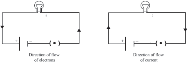
Conventionally, the direction of an electric current is taken as opposite to the direction of an electric charge. Hence, electric current flows from the positive terminal to the negative terminal via the bulb.
What makes the electrons, and hence the current to flow in a circuit?
It is the difference in potential that tends to push the electrons across the circuit, which in turn is responsible for the flow of current.
You know that potential difference between two points can be compared with the difference between the water levels in two connected containers.
In the same way, the flow of electric current can be compared with the flow of water between the water columns. Water always flows from higher level to lower level. Similarly, electric current always flows from high potential to low potential.
Do you know how the flow of electric current occurs?
The answer is very simple. The flow of electric current occurs because of the flow of charged particles. In metallic conductors, the charged particles are electrons. Therefore, we can say that the flow of electric current is nothing but a flow of electrons.
The Direction of Electric Current
By convention, we consider the direction of electric current to be the same as the direction of flow of positively charged particles. As electric current in a conductor is the flow of electrons, which are negatively charged particles, the direction of flow of current is opposite to the direction of flow of electrons.
Amount of Electric Current
By now, we know that electric current is the flow of charged particles in a conductor. Therefore, the amount of current is also related to the amount of charge. The amount of electric current in a conductor is the flow of total charge per unit time.

The unit of electric current is ampere (A). It is defined as the flow of one coulomb of charge in one second.

Ohm’s Law

Construct a simple electric circuit using a battery having 5 cells of equal potential V, a resistor of resistance R, and a switch. Connect a voltmeter and an ammeter across and along the resistor respectively (as shown in the given figure). Make sure that initially the circuit is connected with only one cell. Now, switch on the circuit and measure the readings in both the ammeter and the voltmeter. Note these readings in the table given below.
Now, connect the circuit with two cells and measure the readings in the voltmeter and the ammeter. Repeat the process using three, four, and five cells respectively and note the readings in each case. An example is tabulated below.
| Number of cells | Potential difference between M and N | Current flowing in circuit (A) |
| 1 | 2 | 1 |
| 2 | 4 | 2 |
| 3 | 6 | 3 |
| 4 | 8 | 4 |
| 5 | 10 | 5 |
Now, plot a graph between the potential difference and the current for these five readings. Draw the potential difference on x-axis and current on y- axis. You will observe that the graph between the two quantities comes out to be a straight line. What is the significance of this straight line?

You know that current is a flow of electric charge. These charges flow from one point to another when a potential difference exists between the two points. How do we relate potential difference with current?
If you calculate the ratio VIVI for all five cases, then you will get the same value approximately. This implies that the ratio VIVI is constant. It does not depend on the number of cells used in the circuit. Hence, we can say that the potential difference (V) is directly proportional to current
(I). Thus,
V ∝ I
This relation is known as Ohm’s law.
According to this law, under constant physical condition i.e. constant temperature, pressure etc. the applied potential difference is directly proportional to the current flowing in the circuit.
Or, V = RI
Where R is a constant of proportionality called resistance of the resistor, it tends to resist the flow of charge through a conducting wire. Its SI unit is Ohm (Ω).
Thus, we can write Ohm’s law as
I = V/R
Hence, according to Ohm’s law, current is
1. Directly proportional to potential difference.
2. Inversely proportional to resistance.
If the potential difference is doubled (keeping resistance the same), current will also get doubled. On the other hand, if resistance is doubled (keeping potential difference the same), current will reduce to half.
Ohmic resistors:
Conductors which follow the ohm’s law at constant temperature are called ohmic resistors. Examples: All metallic conductors (Copper, Aluminium, silver etc.), copper sulphate solution with copper electrodes, and dilute sulphuric acid, etc.
A straight line graph passing through the origin is obtained between potential difference V and current I for such resistors. This means that the ratio of V and I i.e. R is constant for all values of V or I.
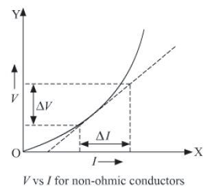
Non-ohmic resistors:
Conductors which do not follow the ohm’s law are called non-ohmic resistors. Examples: LED, solar cell, junction diode, transistor, bulb filament etc.
A non-linear graph is obtained between potential difference V and current I for such resistors. This means the ratio of V and I i.e. R does not remains constant for such resistors.
Example:
In an electrical circuit, what is the resistance offered by a bulb to a flow of charge if the ammeter and the voltmeter show a reading of 2 A and 12 V respectively?
Solution:
Given that,
Potential difference, V = 12 V
And current, I = 2 A
According to Ohm’s law, potential difference
V = IR
Or, R=VIR=VI

Hence, 6 Ω resistance is offered by the bulb to the flowing charge.
Example:
In the given electric circuit, the potential of the battery is 24 V.

When a copper wire is connected between points M and N, the ammeter reads 5 A, whereas when a chromium wire of the same length and thickness is connected between points M and N, the ammeter reads 2 A. Can you tell which wire offers greater resistance to the flow of charges?
Solution:
Given that,
potential difference for both the wires, V = 24 V
For Copper wire:
Current, I = 5 A
On applying Ohm’s law, we get
⇒ V = IR

For Chromium wire:
Current, I = 2 A
On applying Ohm’s law, we get
V = IR
Or, R = V / I
∴ Ro = 24 V / 2 A = 12 Ω
Since, Rcr is greater than Rcu, chromium wire will offer greater resistance in comparison to copper wire. Hence, Ohm’s law shows that chromium wire is a poor conductor of electricity as compared to copper wire.
Electric Resistance and Electron Drift
We know that good conductors have free electrons on their surfaces. These electrons move randomly in all directions in a conductor, such that there is no net flow of electrons in a particular direction. Hence, no current flows in a conductor till some external potential difference is not applied. Now, the question is what happens in a conductor when an external potential is applied to it? To understand this, we first need to know how free electrons move in a conductor.
There are a few assumptions we make to understand the microscopic view of the movement of free electrons. These are—
Electrons are free to move anywhere in a conductor. This can easily be understood by the fact that the force exerted by the protons on the free electrons is very small.
As the sizes of the electrons are very small as compared to those of the atoms, we also assume that electrons do not collide with one another, but only collide with the atoms of a metal. Thus, electrons change directions continuously.
So, when we apply an external field, electrons drift very slowly in one particular direction by slightly modifying their random motion. Electrons do not start moving in a straight line in a particular direction when external potential difference is applied. Their movement is still random. It is just that there is a net displacement of electrons in the direction opposite to that of the field. For the sake of simplicity, the electrons in the following figure are shown to be drifting in only one particular direction.

The motion of electrons continues to be random even after an external field is applied because they keep colliding with the other atoms. Hence, we can conclude that these collisions slow down the passage of current, or we can also say:
‘The more the number of collisions, the more is the resistance offered by a conductor.’
Electric resistance can be defined as the obstruction or opposition to the drifting electrons.
Electric resistance completely depends on the nature of a conductor.
Units of Resistance:
Resistance is measured in ohms (Ω).
If a current of 1 amp flows through a conductor, when its ends are maintained at a potential difference of 1 V, then the conductor is said to have a resistance of 1 Ω.
Factors Affecting Resistance of a Conductor
Do you know why it is advisable to use thick conducting wires in wiring?
This is related to the amount of resistance offered by wires used in circuits. We know that resistance is a natural tendency of the conductors to oppose the flow of electric charge from it. Hence, it causes a loss of electricity and should be minimised. This can be achieved by using thick conducting wires.
Here, we will discuss the different factors on which resistance of a conductor depends.
Factors that affect resistance
Construct an open circuit with open ends M and N (as shown in the figure). Take six pieces of wire with dimensions as given below.
Case (i) Copper wire → of length MN of the given cross-section.
Case (ii) Copper wire → of length greater than MN having the same cross-section.
Case (iii) Copper wire → of length less than MN having the same cross section.
Case (iv) Copper wire → of length MN but a comparatively thicker cross-section.
Case (v) Copper wire → of length MN but comparatively a thinner cross-section.
Case (vi) Chromium wire → of length MN and of same cross-section as in case (i).

Connect copper wire of case (i) between the open points M and N, and note the readings in the ammeter. The reading will give you the amount of current flowing through the copper wire.
Similarly, connect wire of case (ii) and note the reading in the ammeter. Repeat the process with the remaining four wires and make a table of your readings in each case. Scrutinize the readings and compare them with the dimensions of the wire. Does the current depend on the length, cross-section, and nature of the material used?
You will notice that the amount of current that flows through wire in case (i) is greater than that flowing through wire in case (ii). What does this mean? This means that a long wire offers greater resistance in comparison to a short wire. Also, resistance decreases with an increase in the cross-sectional area.
Similarly, if you allow the current to flow in each wire for a relatively longer period, you will find that there is a decrease in current. Hence, from this activity we can say that resistance of a conductor depends on the following:
I. Length of the conductor
II. Cross-sectional area of the conductor
III. Temperature of the conductor
IV. Nature of the material used
Symbol of resistor

I. length of the wire
Resistance is directly proportional to the length of the conductor i.e.
R ∝ l
Where, l → length of the conductor
II. Cross-section of the conductor
Resistance is inversely proportional to the area of cross-section of the conductor i.e.
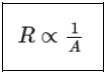
A → area of cross-section
• Since conductors have a circular cross-section, the area of cross-section is directly proportional to the square of the radius of the cross-section i.e.

r → radius of the cross-section
When the diameter of a conductor is made double, its resistance becomes one fourth.
Thus, we can write,
R ∝ l/A
Or,
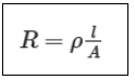
Where, p is the proportionality constant, called the electrical resistivity of the material of the conductor. It is also known as specific resistance.
The resistivity or specific resistance of a substance is equal to its resistance, if it has a unit length and unit cross-sectional area.
The SI unit of resistivity is Ω m (Ohm-meter).
• Resistivity is the characteristic property of a material. It only depends on the nature of the material and not its dimensions. This is one of the major differences between resistance and resistivity. But like resistance, resistivity also varies with temperature.
Conductivity
The reciprocal of resistivity is known as conductivity. Its SI unit is ohm−1 metre−1 or Ω−1
m−1 or siemen metre−1.

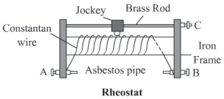
Rheostat or variable resistance:
It is a device used in an electric circuit by which we can continously change the resistance of the circuit. It does this by varying the length of the resistance wire used in circuit.
Graphic
Resistance box
It is a box consisting of several resistances of different values connected in series. As per the circuit requirement, resistance of any desired value can be achieved by removing or inserting the key from the box.

III Temperature of the conductor
Experimentally, it is found that resistance of a conductor increases with the temperature and vice-versa. But resistance of alloys such as nichrome, constantan etc. is only slightly affected by temperature. Hence, alloys are better suited in electrical circuits.
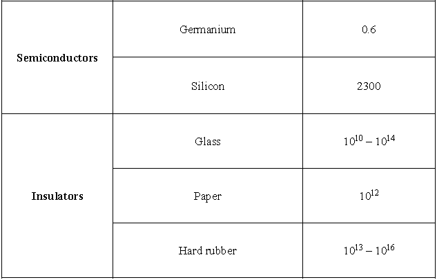
Semiconductors
Germanium and silicon offer resistance lying between the resistances of conductors and insulators. Hence, these are called semiconductors. Their resistivity decreases with temperature, in contrast to conductors and alloys. Semiconductors have great importance because their conducting properties change with temperature, impurity, concentration etc.
IV Nature of the material
In the above activity, you will notice that the reading in the ammeter for wire in case
(i) is greater than the reading for wire in case (vi). This means that a copper wire offers less resistance than a chromium wire of the same length and cross-sectional area, on the nature of the material used. Hence, it can be deduced that the resistance of a conductor depends on the nature of the material used.
The following table shows the resistivity of some materials at 20 °C.


Interesting Fact:
Superconductivity
The phenomenon of superconductivity was discovered by K. Onnes in 1911. He discovered that the resistance of mercury fell abruptly to zero on lowering its temperature below 4.2 K. This means that if a current is passed through a superconducting wire it will continue to flow forever!
Emf and Internal Resistance of Cell; Resistance in Series and Parallel
Emf (E)
• Potential difference between the two electrodes of the cell in an open circuit is called emf of the cell.
• It is also defined as the amount of work done per unit charge in taking a positive charge around the complete circuit of a cell (i.e. in the electrolyte present inside the cell as well as in the circuit
outside the cell). Its SI unit is volt (V).
E = W / q
where, W is the work done in taking a positive around the complete circuit of a cell.
Factors affecting emf of a cell
Emf of a cell is its characteristics property which depends only on two factors:
• the material of the electrolyte
• the electrolyte used in the cell
Terminal voltage of a cell (V)
• Potential difference between the two electrodes of the cell in a closed circuit is called emf of the cell.
• It is also defined as the amount of work done per unit charge in taking a positive charge around the circuit connected across the terminals of a cell (i.e. only in the circuit outside the cell). Its SI unit is volt (V).
V = w’/q
where, W’ is the work done in taking a positive charge around the circuit connected across the terminals of a cell.
Voltage drop in a cell (v)
• It is defined as the amount of work done (w) in taking a unit positive charge through the electrolyte inside a cell. Its SI unit is volt (V).
V = w/q
Relation between emf (E), terminal voltage (V) and internal resistance (r)
Following the law of conservation of energy, we have
W = W’ + w
Dividing both sides by q, we get

Internal resistance (r) of cell
• Resistance offered by the electrolyte of the cell to the flow of electric current through it. If I is the current flowing through the cell of internal resistance r, then voltage drop due to this internal resistance is v =Ir.
Factors affecting internal resistance of a cell
• The surface area of electrodes: internal resistance of a cell increases with increase in surface area of electrodes
• The distance between the electrodes: internal resistance of a cell increases with increase in distance between the electrodes
• The temperature of the electrolyte: internal resistance of a cell increases with increase in temperature of the electrolyte
• The concentration of the electrolyte: internal resistance of a cell increases with increase in concentration of the electrolyte
• The nature of the electrolyte: internal resistance of a cell increases with increase in ionic nature of the electrolyte
Relation between emf (E), terminal voltage (V) and internal resistance (r)

E − emf of cell
r − Internal resistance of the cell
R − External resistance
K − Key
V − Voltmeter
• The key K is closed and a current I flows in the circuit.
According to Ohm’s law,

• Let V be the terminal potential difference. The terminal potential difference V is less than emf E of the cell by an equal amount, which is equal to potential drop across external resistance R i.e.,
∴ V = E − Ir
Also, terminal potential difference is equal to potential differences across external resistance.
V = IR
From equation (1),

Combination of resistors
Resistors in series
• Two or more resistors are said to be connected in series, if same current passes through each of them, when a potential difference is applied across them.

• Equivalent resistance, RS = R1 + R2 + R3
• Equivalent resistance is always greater than the largest resistance present in the combination
• E = V1 + V2 +V3
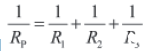
Resistors in parallel
• Two or more resistors are said to be connected in parallel, if potential difference across each of them is equal to the applied potential difference.

• Equivalent resistance (RP),
• Equivalent resistance is always less than the smallest resistance present in the combination
• I = I1 + I2 +I3
Electric Power and Energy
We use electricity to run various electrical appliances such as bulbs, tube lights, refrigerators, electric heaters etc. in our homes. Do you think all these home appliances consume an equal amount of electricity at a given time?
No, the amount of electricity consumed by an electrical appliance depends on the power rated on that appliance. For example, for 220 V potential supply, a tube light of rated power 40 W draws 0.18 A of current, whereas a bulb of rated power 100 W draws 0.45 A of current.

How can you determine the rate of consumption of energy by a given appliance?
Electric power
Electric power is defined as the rate of consumption of energy or simply the rate of doing work.
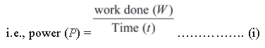
The work done by current (I) when it flows in a potential (V) for time (t) can be given by
W = VIt …………………. (ii)

∴ Electric power or P = VI
The SI unit of power is watts (W).
Also, the energy dissipated or consumed by an electric appliance per unit time is given by
It is also an equation for electric power.

i.e., P = I2R
Now, according to Ohm’s law
⇒ V = IR
⇒I = V/R
If we substitute the value of I in the equation of power, we get

Hence, we get the expression for electric power as
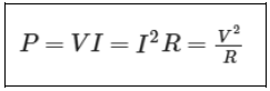
Where, 1 W = 1 V × 1 A = 1 V A
1 watt is defined as the power consumed by an electrical circuit that carries a current of 1 ampere, when it is operated at a potential difference of 1 volt.
• Since Watt is a very small unit, we define a larger unit of power as kilowatt (kW). Thus,
1 kW = 1000 W
For practical purposes, we define kilowatt hour (kWh) as ‘unit’ where,
1 unit = 1 kWh = 1000 W × 1 hour
= 1000 W × 3600 s
= 36 × 105 Ws
= 3.6 × 10⁶ J
1 kWh is also the commercial unit of electric energy.
Note that electricity is a flow of electrons and nothing else. Hence, power stations only make the electrons flow through conducting wires for which they charge us. They do not create or generate the electrons.
Prepare a list of electrical appliances commonly used in homes. Note down the respective watts rated on them. Now, try to calculate the amount of current drawn by respective appliances for a constant voltage of 220 V. Complete the table and discuss the result with your friends.

Example:
(i) The amount of current drawn by an immersion water heater is 6.8 A. If the heater is operated on 200 V of potential difference, calculate its power.
Solution:
Given that,
Potential difference, V = 200 V
Current drawn, I = 6.8 A
By definition of electric power, we know that
P = VI
Hence, P = 200 V × 6.8 A
= 1360 W
Hence, power of the given immersion heater is 1360 W.
(ii) What is the monthly cost of energy to operate the given immersion water heater 3 hours/day at Rs 5.00 per unit?
Solution:
Power of the heater is 1360 W.
Energy consumed by it per day = 1360 W × 3 hours / 1 day
Hence, energy consumed by it in 30 days = 1360 W × 3 hours / 1 day × 30 days
= 122400 W
= 122.4 kWh
= 122.4 units
Now, the cost of energy for one unit is Rs 5.00
∴ Cost of energy for 122.4 units will be 5 × 122.4 = 612
Hence, the monthly cost of energy of the heater is Rs 612.
Heating Effect of Current
It is winter time. Dilip and his younger sister Meenakshi are studying in their room. A room heater has been kept to keep the temperature of the room above normal. This helps them bear the cold. Dilip has read in his science book that electricity is required for operating any electrical device. He wonders how a room heater can emit a large amount of heat.

The heater emits heat due to the conversion of electrical energy into heat energy. This phenomenon is known as the heating effect of current. Let us learn more about this effect.
A wire (say nichrome wire) becomes hot when electric current is allowed to flow through it for a relatively long time. This phenomenon is known as the heating effect of electric current.
Joule’s Heating
We know that current begins to flow through a wire when it is connected with a source. All wires offer some resistance to the flow of current. To maintain a uniform supply of current, the source must expend its energy (because of which the source eventually gets exhausted). Part of this energy is used for maintaining the supply of current, while the rest is dissipated in the form of heat. This dissipated heat is responsible for the heating of the wire.
The heating effect is more prominent in wires of high resistance. For example, if we take nichrome and aluminium wires of equal length and cross sectional area, and pass an equal amount of current for the same time, we will observe that the nichrome wire gets more heated than the aluminium wire. This happens because nichrome offers more resistance to the flow of current than aluminium.
When a current (I) flows through a resistor of resistance (R) for time (t), the amount of heat produced (H) is given by
H = I2Rt
This is called Joule’s law of heating. This law suggests that the heat produced in a resistor is directly proportional to the
1. square of the current flowing through the resistor, i.e., H ∝ I2
2. resistance of the resistor, i.e., H ∝ R
3. time for which the current flows through the resistor, i.e., H ∝ t
Thus, we can infer from Joule’s heating effect that an appliance offering more resistance to the flow of electrons releases more heat per unit time, keeping the potential of the source constant.
The Joule’s law of heating can have other forms as

Example: A room heater can offer a maximum resistance of 100 Ω when 5 A current flows through it for one minute. What is the maximum amount of heat produced by the heater?
Solution:
Current, I = 5 A
Maximum resistance, R = 100 Ω
Time, t = 1 min
= 60 s
Using Joule’s law of heating, the heat produced is given as H = I2Rt
∴ H = (5)2 × 100 × 60
= 150000 J
Hence, the room heater will produce a maximum of 150000 J of heat in one minute.
The heating effect of current is used in various heating appliances such as electric irons, room heaters, water heaters, hair dryers, geysers, etc. In all these devices, electrical energy is converted into heat energy, which is governed by Joule’s heating effect.
Let us learn about the functions of some heating devices.
1. Electric heater
An electric heater consists of a long coil of wire arranged on an insulating sheet, as shown in the given figure. When electric current is allowed to flow through this coil, it turns red hot because of the heating effect of current. As a result, it provides a specific amount of heat, which can be used for different purposes.
2. Electric Iron
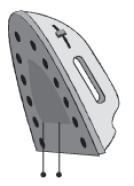
An electric iron consists of a thin metal plate that gets heated when electric current flows through it. This, in turn, heats the thick iron base of the device.
3. Water heater
An electric water heater consists of a coil of wire that gets heated when electric current flows through it. This, in turn, heats the water in which the heater is completely immersed.
Do You Know?
Edison and his bulb

Thomas Alva Edison (1847−1931) was one of the greatest inventors in the history of science. He had one thousand inventions to his name besides the electric bulb. The bulb invented by him was comparatively long-lasting because he used a filament made of a metal having a high melting point. Now-a-days, tungsten filament is used in the electric bulb because it does not melt easily.
4. Electric bulb

A bulb consists of a filament that radiates heat and light when current flows through it. The filament of a bulb is made of tungsten coil. The flow of current causes the filament of the bulb to heat up to an extremely high temperature such that it starts emitting light.
Caution: Do not touch heating devices directly because they can cause your fingers to burn severely.
All heating devices draw a large quantity of electricity to heat the respective appliances. However, bulbs are designed to emit light only. Hence, there is wastage of electricity in the form of heat. This wastage of electricity is reduced by replacing these electric bulbs by compact fluorescent lamps (CFLs). A CFL is shown in the given figure.

List some heating devices that are being used in your home.
Until now, we have discussed the uses of the heating effect of current in situations in which it is allowed to flow through special devices. However, what happens if a large amount of current suddenly flows through a normal wire?
In such an unfavourable situation, the wire becomes hot and eventually melts down. This can cause serious damage to the different circuit components connected to it. In order to avoid such a situation, a fuse element is joined along with the circuit.
5. Electric fuse

Electric fuses are devices used for the protection of expensive electric devices such as bulbs, TVs, fans, etc. A fuse element has a very low melting point. Hence, it melts quickly whenever there is a slight increase in the amount of current. As a result, the path of the current is broken. This protects the device from being damaged by the abrupt flow of current. The given figure shows a simple electric fuse that is commonly used in households.
Power Transmission and Distribution
Electricity produced in a power station is transmitted for industrial and domestic uses with the help of transformers, transmission wires, towers, etc.
After generating electricity, a power transformer is used, at heavy load, for its transmission. The power transmission transformer is usually large in size.
At the initial stage of power transmission, a step-up transformer is used to increase the voltage of electricity.
Transmission loss
Energy loss in the form of heat, during the transmission of electricity, is minimal when the electricity is transmitted at a high voltage for a given power. This is because at high voltage, current flowing through the wire is minimal.
In an electric line, energy is lost in the form of heat. This loss is known as transmission loss.
Heat developed in the electric lines is given by H = I2 Rt
And electric power is given by P = V × I
If voltage is larger, current is smaller for the same power. Hence, the energy loss is less.
That is why a step-up transformer is used at the initial stage of transmission network.

Different stages of power distribution
Heat loss in the transmission network depends on the following three factors:
(i) Magnitude of the electric current flowing through the wires
(ii) Resistance of the wires
(iii) Time for which current is flowing
Star connection
At the last stage of transmission, a distribution transformer is used for the distribution of electricity at low voltage. This voltage is lesser than 33 kilo volts for industrial purposes and around 220v for domestic purposes. The size of a distribution transformer is smaller than a power transmission transformer.

Four lines come out of the distribution transformer. Let us see how these lines come out.
Wires are connected in star mode connection in the secondary coil of the distribution transformer as shown in the figure.

We get four lines out of the distribution transformer; three phase lines (P1,P2 and P3) and one neutral line(N). Each phase has the same frequency but different voltages.
From this distribution system, we can see that P1 and N line are used for the domestic purpose.
Domestic Electric Circuit

Vikram has read in his science book that electricity reaches our homes, schools, factories etc. through thick aluminum and copper wires. The supply voltage is 220 V. He has scrutinized some electrical appliances such as bulbs, heaters, and refrigerators in his house and found that they all operate at 220 V. He wonders how these appliances run simultaneously with only 220 V
supply voltage.
Vikram’s confusion can be sorted out by understanding the concept of domestic electrical circuits.
Domestic wiring
Electricity is transferred to our homes through a pair of insulated copper or aluminum wires. This pair consists of a red color wire (called live wire, L), and a black color wire (called neutral wire, N).
In addition to these wires, a green color wire known as the Earth wire, E is also connected with the circuit. In India, 220 V potential is supplied through live wire, while neutral wire has ground potential of zero volts.

In the above diagram, the pair of wires L and N first enter the main box, which is placed outside the house. From here, live wire L goes into the main fuse F1 having a high rating of about 50 A. Then, both wires enter the electricity meter that records the electricity consumed in units, where 1 unit = 1 kWh = 3.6 × 10⁶ J. The wires then go to the main switch, S. Electricity supplied to the house can be cut off using this switch.
The extensive use of electricity is due to the convenience and usefulness associated with this form of energy. Domestic uses of electricity include lighting, heating, cooling and nowadays, even cooking. The electricity supply board usually provides alternating current at 220 V.
Alternating current consists of three phases or what we see as wires of three different colours.
1. Red wire is the live wire
2. Black wire is the neutral wire
3. Green wire is the earth wire

Here, the red and the black wires are called the supply wires, while the green wire is for safety.
Why use the earth wire?
Earth wire is quite necessary in a household appliance. It causes a leaking current to flow harmlessly to the ground, thereby preventing the user of the appliance from getting an electric shock.
Importance of Earthing

We can receive an electric shock on touching a running appliance. This is caused by the leakage of current from the appliance. Earthing provides a safety measure against the electric shock, caused by the leakage of current. A third wire called the Earth wire (E) is also used in domestic wiring. This wire has green insulation over it. A copper plate connected to the main switch via the meter is connected at one end of this wire, E.
Sometimes, the insulation of a live wire burns due to excessive heating. A naked live wire may lead to an electrical shock. To protect the appliance against an electrical shock, its metallic case is connected with the Earth wire. Hence, a domestic socket is composed of three wires, namely the live wire, neutral wire, and Earth wire.
Open and Closed circuits
When the two ends of an electrical circuit are not connected, no current flows through the circuit. We say that the circuit is not complete and call it an open circuit. No current flows through the circuit in this situation.
On the other hand, when the two ends of an electrical circuit are connected and the circuit forms a closed loop, we call it a closed circuit.
Every circuit in ‘switched-off’ condition is an open circuit.
Switches: It is a device which is connected in the live wire so as to turn ‘ON’ or ‘OFF’ the current in the circuit.
Types of switches:
1) Single pole switch: A single pole switch is a simple switch which is used with an appliance to start or stop the flow of current in it. This switch only disconnects the live wire from the appliance.
2) Double pole switch: A double pole switch is a main switch in the distribution board, used to switch on or off the main supply. This switch disconnects both live and neutral wires simultaneously. We often use such switches in a staircase etc. Why switch should always be connected in the live wire?
• If the switch, connected to live wire which is at high potential, is turned off, then the switch cuts the path of current to the appliances connected to the live wire. This is because, in this case, both the live and neutral wires connected to the ends of the appliances come at zero potential and hence does not allow current to flow in the circuit. Thus, if required, we can safely carry out repairs for our appliances as appliances in these case also are at zero potential.
• But if the switch, connected to a neutral wire which remains at zero potential, is turned off, then also current will not flow through the appliances in this case as the circuit is not closed. But the live wire (or appliances) still remains at high potential in this case. So, it would becomes dangerous to carry out repairs in appliances as current would flow from the appliances to the person’s body (body being at low potential).
Working of dual control switch/ double pole switch
Two dual control switches S1 and S2 are connected at the top and bottom of the staircase, respectively. Now, the bulb connected to both the switches can be put on or off using any of the two switches.
Situation (a): In this situation, bulb does not glow as live wire connecting the point c of switch S1 (in ‘OFF’ position) through point b and c of switch S2 (in ‘ON’ position) is not making a complete circuit.

Situation (b): In this situation, switch S1 is pressed ‘ON’ and switch S2 is in same position (i.e. in ‘ON’ position). The live wire, which provides the current to point c of S1 from point b and c of switch S2 , now gets connected to point b of switch S1. Hence, the circuit is complete and thus the current flows through the bulb and the bulb glows.
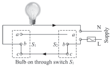
Situation (c): In this situation, switch S1 (in ‘OFF’ position) will disconnect the path of the current from point c to b of switch S1 but joins the point a to b of S1 creating a new path for the current. Simultaneously, switch S2 (in ‘OFF’ position) will disconnect point c from b and connect point b with a of switch S2. Again the current flow from S2 to S1 through point b to a of S2 to a to b of S1. Hence, the bulb glows.

Series and Parallel circuits
Depending upon how the appliances are connected to each other, domestic electrical circuit can be of two types—parallel circuit and series circuit.
When the appliances are connected end-to-end one after another, the circuit is called series circuit.
When the appliances are connected parallel to each other between two points, the circuit is called parallel circuit.

In domestic circuit, parallel circuit is always preferred over series circuit.
Electric fuse
An electric fuse is a safety device that protects the wiring against excessive heating caused by an excess supply of current. It melts when heavy current flows through the circuit, thereby causing the circuit to become open.

Characteristic of electric fuse
• Fuse wire has low melting point. It is generally made up of an alloy of lead and tin.
• Fuse wire is always connected in the series with the live wire. Its resistance is higher than that of the copper wires. So it gets heated up much faster than the copper wire when excessive current flows through it.
• Current rating of the fuse wire decides its thickness. More the current rating of the fuse wire, more will be its thickness.
Miniature circuit breaker (MCB)
An MCB is a device which functions as a fuse, but does not require replacement. MCB falls down to break the circuit when heavy amount of current flows through it. Once the fault is rectified, the MCB is reset.

Excessive flow of current can be caused by any of the following two cases:
I. Short circuiting

Short circuiting occurs when naked live and neutral wires touch each other. In such a case, the resistance of the circuit becomes very less. Now, according to Ohm’s law, current is inversely proportional to resistance. Thus, the lowering of resistance of the circuit raises the current to a significant amount. As a result, the wires become hot and a spark is caused by Joule’s heating effect of current. This situation is known as short circuiting.
II. Overloading
A large amount of current is withdrawn from the circuit, when a large number of electrical appliances of high power-rating are switched on at the same time or connected in a single multiplug. This situation is called overloading. It may even lead to a fire in the circuit.

To prevent any damage by short circuiting or over loading, an electric fuse (that consists of a low melting point wire) is used. The wiring of the circuit is made of low resistance copper wire of a certain thickness. This allows only a maximum amount of current to flow through it, which is called its safe limit.
If an amount of current flowing through a circuit exceeds its safe limit either caused by short circuiting or over loading, the excess heat caused by Joule’s heating melts the wire. This results in the breaking of the circuit, thereby preventing the appliances from damage.
Depending on the thickness, fuse elements are rated as 1 A, 2 A, 3 A, 5 A, 10 A, 15 A, and so on. For example, a 10 A fuse element melts and breaks if the current exceeds its limit of 10 A. Short circuiting and overloading are the major hazards related to electricity. There are various other hazards of electricity against which we should be cautious and should take precautions.
Precautions to be taken while using electricity:
• Never touch switches with wet hands.
• Ensure all electrical appliances are properly earthed.
• Ensure MCB, fuse and switch are connected to live wire.
• Never repair an appliance while in use.
• The wiring used must be properly insulated.